Orthodontic bracket

a bracket and orthodontic technology, applied in the field of orthodontic brackets, can solve the problems of occlusion change between the upper and lower teeth, frequent reset of the bracket body and the arch wire with respect to each corresponding tooth, and force patients to carry a heavy burden, so as to relieve patients of burden

Inactive Publication Date: 2007-06-07
KIMURA NORIFUMI
View PDF6 Cites 19 Cited by
  • Summary
  • Abstract
  • Description
  • Claims
  • Application Information

AI Technical Summary

Benefits of technology

[0013] The present invention has been undertaken to eliminate troublesome reset of a bracket body and an arch wire with respect to each corresponding tooth unlike the conventional technology, and its object is to provide an orthodontic bracket that enables orthodontic treatment to be performed without requiring reset of the bracket body and the arch wire even in an advanced stage of the orthodontic treatment.
[0014] To attain the above object, an orthodontic bracket according to the present invention comprises a bonding plate having a bonding surface matching a curve of a tooth; a base having a bottom surface united with the bonding plate and an upper surface as a sliding surface parallel to a long axis of the tooth, and taking an approximately rectangular shape in plan with a convex curve formed in accordance with the long axis of the tooth; and a bracket body set on the sliding surface of the base in such a way that the bracket body may slide along the long axis of the tooth, wherein the base has, on the opposite upper sections of the sliding surface, confronting groove-like parallel rails adapted to let the opposite portions of the bracket body therein slidably, each rail has, at its opposite ends, stoppers to prevent detachment of the bracket body, the sliding surface has, at its widthwise center, a longitudinally-extending visible median line, and the bracket body has, on its upper surface, wire slots arranged approximately orthogonal to the long axis of the tooth.
[0020] Thus, there is no need to reset the bracket body and / or the arch wire every time the orthodontic treatment of the tooth to be orthodontically treated is advanced to the stage necessitating the change in set position of the bracket with respect to the tooth to be orthodontically treated. Accordingly, the orthodontic bracket of the present invention enables the orthodontic treatment to be performed in a shorter period of time, and besides, may contribute to relieve the patient from one's burden by far.
[0021] Further, the orthodontic bracket of the present invention has the base of the convex-curved shape in accordance with the vertical direction of the tooth, permitting more successful matching of the convex-curved base to the tooth side surface to be obtained, and also permitting an installed posture of the bracket body set on the sliding surface of the base to match the tooth side surface more successfully.

Problems solved by technology

Some of important problems involved in bonding of each orthodontic bracket in its accurate posture to the above bracket position of the corresponding tooth are how to select position and / or direction of the bracket body for parallel arrangement between the axis of each wire slot in the bracket body and the linear occlusal plane of teeth, how to select the position and / or direction of the bracket body for alignment between the bracket body and the corresponding tooth, and how to match a gradient of the bracket body to the corresponding tooth side surface.
However, the orthodontic bracket, even after placement of this bracket in its accurate posture in the bracket position of each tooth is achieved, brings about distal or mesial movements of the tooth requiring the orthodontic treatment, with advance of the orthodontic treatment depending on clamping force of the arch wire, resulting in a change in occlusion between the upper and lower teeth.
Thus, the orthodontic brackets of the above types in a conventional technology give rise to such problems that the change in occlusion of teeth with the advance of the orthodontic treatment necessitates a change of bracket position setting, causing frequent reset of the bracket body and the arch wire with respect to each corresponding tooth.
Further, frequent reset of the bracket body and the arch wire requires much time for the orthodontic treatment, and besides, forces heavy burden upon the patients.

Method used


Image

  • Orthodontic bracket
  • Orthodontic bracket
  • Orthodontic bracket

Examples


first embodiment

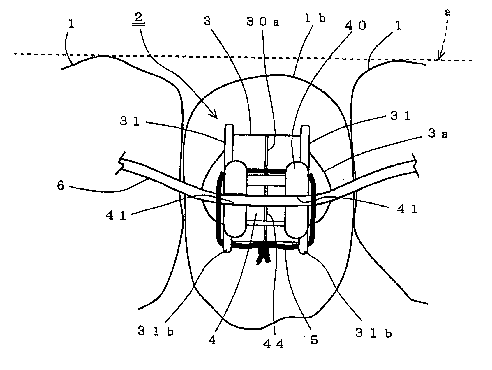
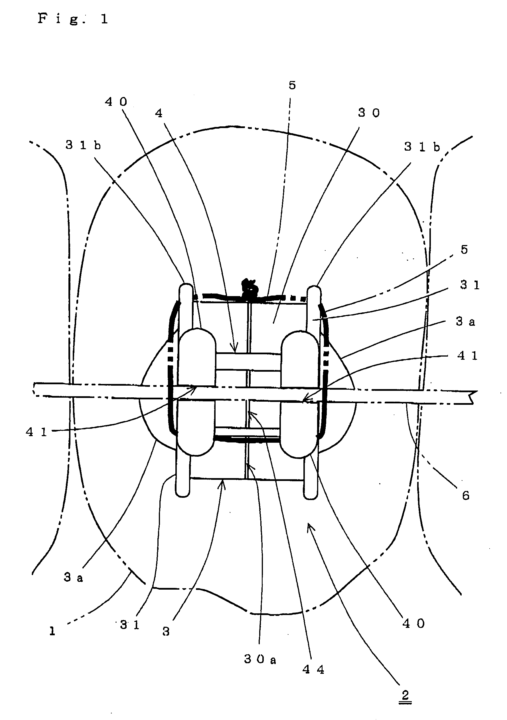
[0045] Referring to FIG. 1, reference numeral 2 denotes an orthodontic bracket placed on a side surface (or a front surface) of a tooth 1 subjected to orthodontic treatment. The tooth 1 in FIG. 1 is shown with its lower part as a gingival side (or a root side of the tooth).

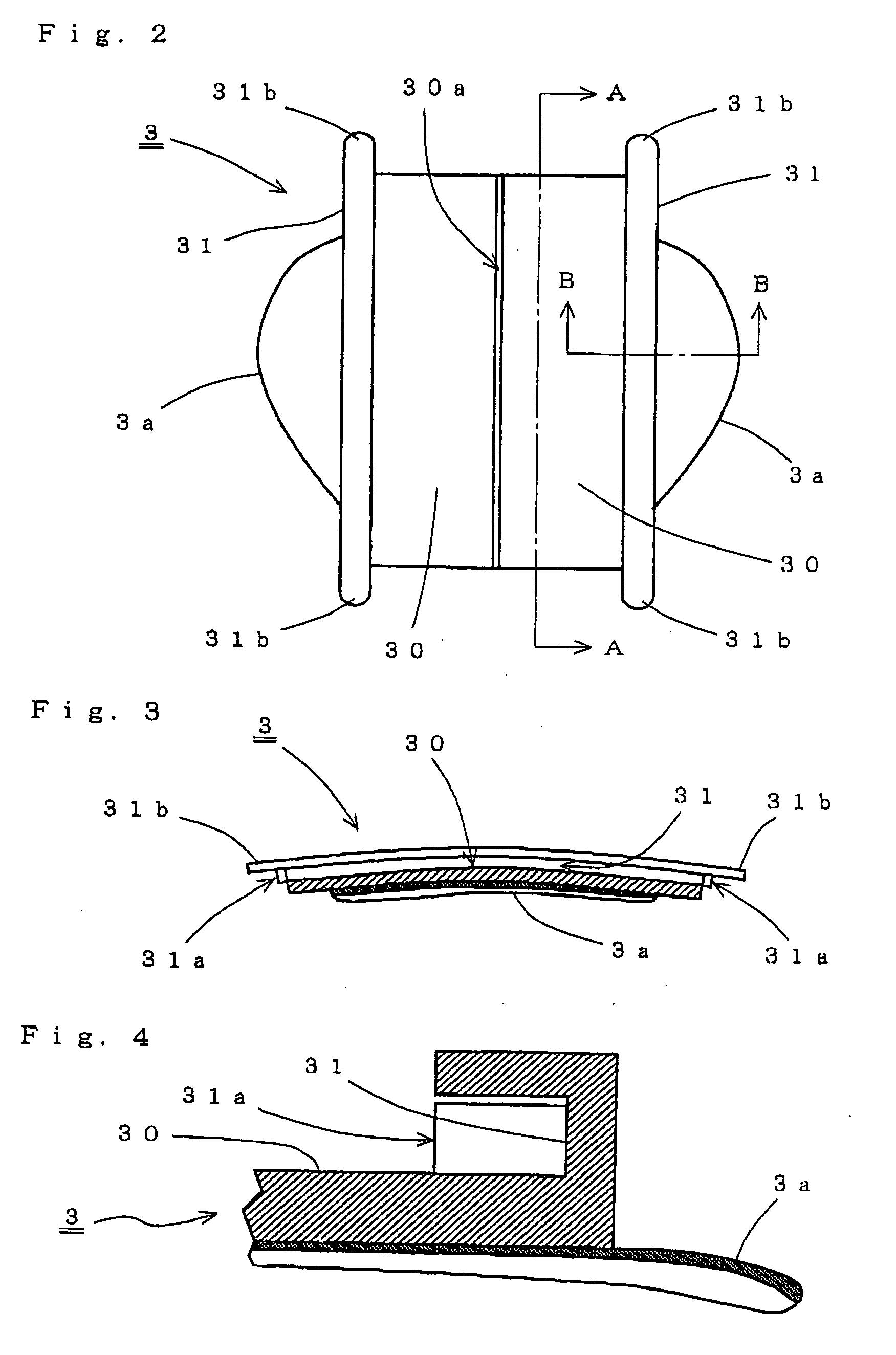
[0046] The orthodontic bracket 2 comprises a bonding plate 3a having a bonding surface matching a curve of the side surface of the tooth 1, a base 3 (see FIG. 3) having a bottom surface united with the bonding plate 3a and an upper surface as a sliding surface 30 parallel to a vertical direction of the tooth 1, and taking an approximately rectangular shape in plan with a convex curve formed in accordance with a long axis (or the vertical direction) of the tooth 1, and a bracket body 4 set on the sliding surface 30 of the base 3 in such a way that the bracket body may slide along the long axis of the tooth 1.

[0047] As shown in FIGS. 1 to 7, the base 3 has, on the opposite upper sections of the sliding surface 30,...

second embodiment

[0058] FIGS. 8 to 10 are views showing the orthodontic bracket of a second embodiment according to the present invention including a modification of the bracket body.

[0059] In the second embodiment, there is provided a sliding plate 46 secured to the bottom of the bracket body 4, in which case, the opposite ends of the sliding plate 46 serve to form the guided parts supposed to be let in the corresponding rail 31 of the base 3. The sliding plate 46 has a bottom surface 46a of a concave-curved shape (see FIG. 10) mating the convex-curved shape of the sliding surface 30 (see FIG. 3) of the base 3. The second embodiment has the sliding plate 46 having the bottom surface 46a of the concave-curved shape as described the above, permitting the base 3 to be so placed on the side surface of the tooth 1 as to ensure that more successful matching of a posture of the bracket body 4 to the curve of the side surface of the tooth is obtainable, in cooperation with the base 3 having the sliding su...

third embodiment

[0077]FIGS. 15 and 16 show a third embodiment of the orthodontic bracket involving use of a fixture substituted for the ligature wire. It is to be noted that configurations and / or arrangements of the base 3 and the bracket body 4 in the third embodiment except a fixture-related portion are the same as those in the second embodiment, and hence, their description is omitted. The same is also applied to fourth and fifth embodiments described later.

[0078] The fixture 5a is in the form of a member taking an approximately U-like shape in plan and composed of a basal part 50 supposed to be arranged in parallel to an outside surface of one rail 31 with the fixture attached to the base 3, and a pair of linear legs 51, 51 extending from and approximately orthogonal to the opposite ends of the basal part 60 in one direction, the linear legs being adaptable to hold the bracket body 4 set on the sliding surface 30 of the base 3 from the upper and lower sides of the bracket body. On the other ha...


PUM


Abstract

An orthodontic bracket placed on a side surface of a tooth for correcting irregularities of teeth is disclosed, which enables orthodontic treatments to be performed without reset of a bracket body and an arch wire with respect to the tooth even in an advanced stage of the treatments. The orthodontic bracket comprises a bonding plate having a bonding surface matching a curve of the tooth, a base having a bottom surface united with the bonding plate and an upper surface as a sliding surface parallel to a long axis of the tooth and taking an approximately rectangular shape in plan with a convex curve formed in accordance with the long axis of the tooth, and a bracket body set on the sliding surface of the base so as to be slidable along the tooth axis. The base has, at the opposite upper sections of the sliding surface, confronting groove-like parallel rails adapted to let slidably the opposite portions of the bracket body therein. Each rail has, at its opposite ends, stoppers to prevent detachment of the bracket body. The sliding surface has, at its widthwise center, a longitudinally-extending visible median line. The bracket body has, on its upper surface, wire slots arranged approximately orthogonal to the above tooth axis.

Description

BACKGROUND OF THE INVENTION [0001] 1. Field of the Invention [0002] This invention relates to an orthodontic bracket useful in correcting irregularities of teeth. [0003] 2. Description of the Related Arts [0004] To subject orthodontic treatment to patients troubled with irregularities of teeth, more than one orthodontic bracket made of a material including metals and resins etc. is usually used. Each orthodontic bracket has a bracket body having, on its upper surface, wire slots adapted to hold an arch wire across the upper surface of the bracket body. Each orthodontic bracket is bonded with an adhesive to a side surface (or a front surface in the case of an incisor target, or a side surface in the case of a molar target) of each tooth subjected to orthodontic treatment. [0005] For bonding each orthodontic bracket to each corresponding tooth side surface, a bracket position is set with respect to each tooth such that the bracket body and the tooth specified as a bonding target (or a...

Claims


Application Information

Patent Timeline
Patent Type & Authority Applications(United States)
IPC IPC(8): A61C3/00
CPCA61C7/14A61C7/16
Inventor KIMURA, NORIFUMI
Owner KIMURA NORIFUMI
Why Eureka
Try Eureka