Diluted oil regeneration in internal combustion engine
a technology of internal combustion engine and engine oil, which is applied in the direction of machines/engines, electrical control, mechanical equipment, etc., can solve the problems of inability to exhibit sufficient lubricating performance of engine oil and inability to consume thermal energy in the engine oil regeneration process, and achieve the effect of sufficient lubricating performan
- Summary
- Abstract
- Description
- Claims
- Application Information
AI Technical Summary
Benefits of technology
Problems solved by technology
Method used
Image
Examples
second embodiment
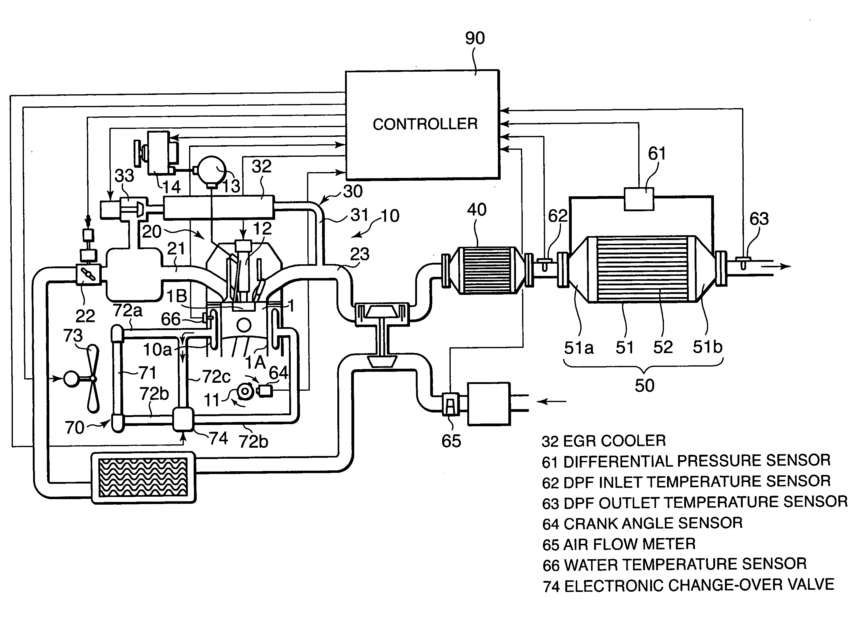
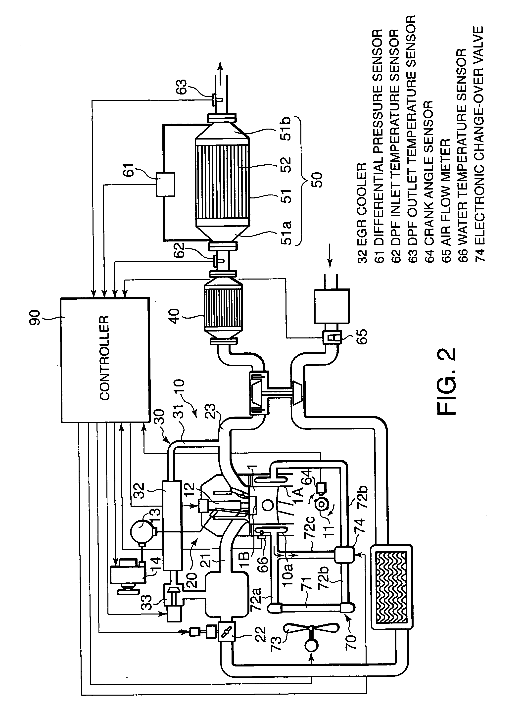
[0076] Referring to FIG. 6 and FIGS. 7A-7D, this invention will be described.
[0077] In this embodiment, the controller 90 executes a diluted oil regenerating routine shown in FIG. 6 instead of the DPF regenerating routine shown in FIG. 5. This routine is executed at fixed time intervals, for example 10 millisecond intervals, independently of control to regenerate the DPF 52.
[0078] This diluted oil regenerating routine may be performed along with a conventional DPF regenerating routine.
[0079] Referring to FIG. 6, in a step S21, the controller 90 calculates the traveled distance of the vehicle. More specifically, the controller 90 may calculate the traveled distance of the vehicle using a product of a gear ratio of a transmission device of the vehicle, which is set in accordance with the rotation speed and load of the diesel engine 10, and the rotation speed of the diesel engine 10, and calculate the traveled distance of the vehicle as an integrated value thereof. It should be noted...
first embodiment
[0084] If the result of the determination indicates that the traveled distance of the vehicle has reached the predetermined regeneration end distance, the controller 90 resets the flag F1 to zero in a step S27, and then terminates the routine. If the traveled distance of the vehicle has not reached the predetermined regeneration end distance, the controller 90 controls the electrically controlled thermostat 74 in a step S26 to raise the engine water temperature, similarly to the step S17 of the Following the processing of the step S26, the controller 90 terminates the routine.
[0085] The predetermined regeneration start distance and the predetermined regeneration end distance are set in advance through experiment.
[0086] Referring to FIGS. 7A-7D, the results of execution of this diluted oil regenerating routine will be described.
[0087] While the traveled distance of the vehicle is small, the controller 90 executes the processing from the step S21 through the step S23 to END upon ea...
third embodiment
[0094] Referring to FIG. 8, FIG. 9, and FIGS. 10A-10D, this invention will be described.
[0095] In this embodiment, the controller 90* executes a diluted oil regenerating routine shown in FIG. 8 in place of the diluted oil regenerating routine of the second embodiment, shown in FIG. 6. This routine is also executed at fixed time intervals, for example 10 millisecond intervals, independently of control to regenerate the DPF 52.
[0096] This diluted oil regenerating routine may also be performed along with a conventional DPF regenerating routine.
[0097] Referring to FIG. 8, in a step S31, the controller 90 calculates the dilution ratio of the engine oil. More specifically, the controller 90 determines the dilution ratio of the engine oil from a flow rate PostQ of the post-injection from the fuel injector 12 and the duration (minutes) of the post-injection, by referring to a dilution ratio map having the characteristic shown in FIG. 9, which is stored in the ROM in advance. This map is s...
PUM
 Abstract
Description
Claims
Application Information
 - R&D
- Intellectual Property
- Life Sciences
- Materials
- Tech Scout
- Unparalleled Data Quality
- Higher Quality Content
- 60% Fewer Hallucinations
Browse by: Latest US Patents, China's latest patents, Technical Efficacy Thesaurus, Application Domain, Technology Topic, Popular Technical Reports.
© 2025 PatSnap. All rights reserved.Legal|Privacy policy|Modern Slavery Act Transparency Statement|Sitemap|About US| Contact US: help@patsnap.com


