Self-heating container

a self-heating container and container technology, applied in the field of containers, can solve the problems of affecting the quality of the seal, not being able to meet the requirements of use, and not being able to meet the requirements of use, and achieve the effect of cost-effective manufacturing and simple design

Inactive Publication Date: 2007-06-14
HEAT WAVE TECH
View PDF67 Cites 35 Cited by
  • Summary
  • Abstract
  • Description
  • Claims
  • Application Information

AI Technical Summary

Benefits of technology

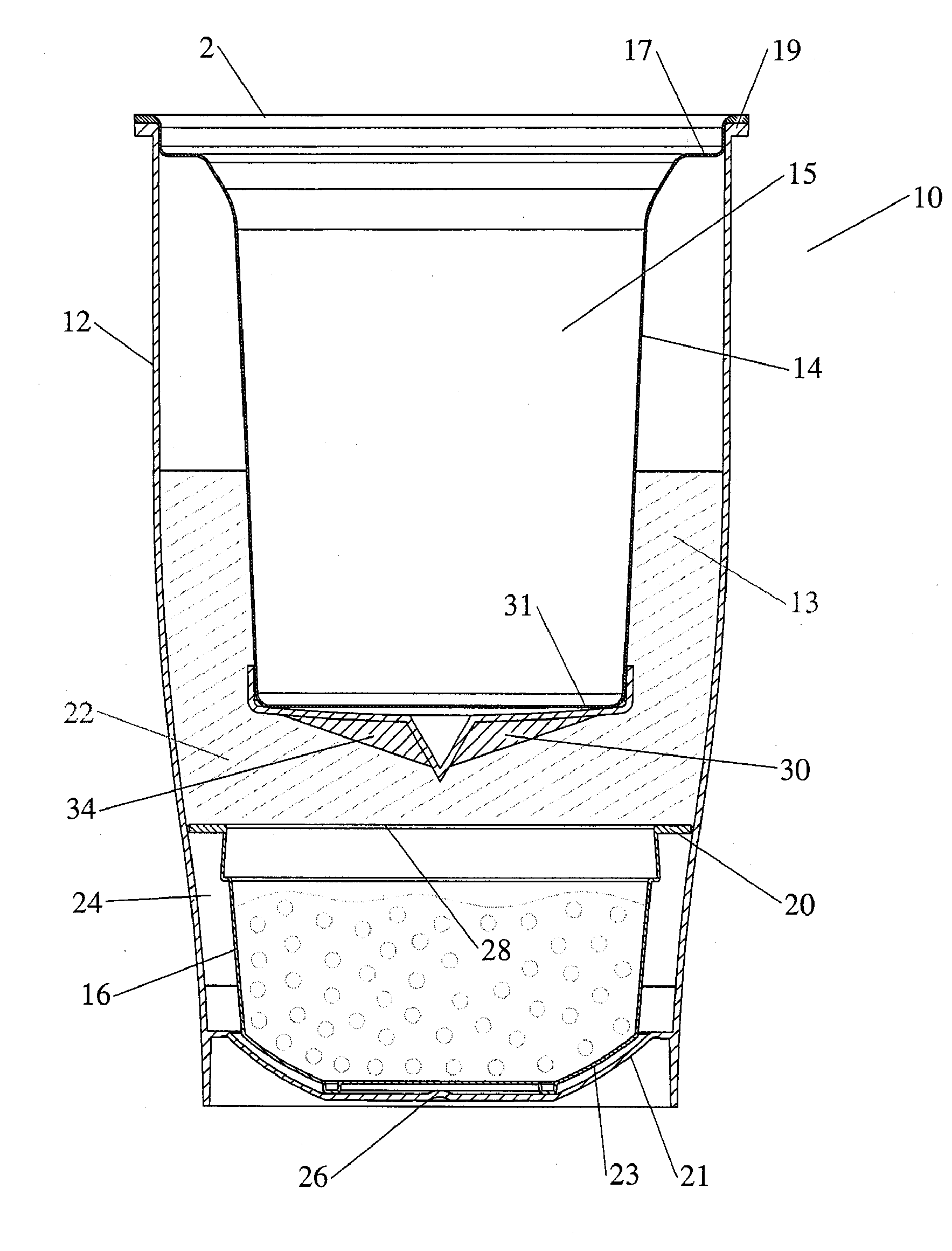
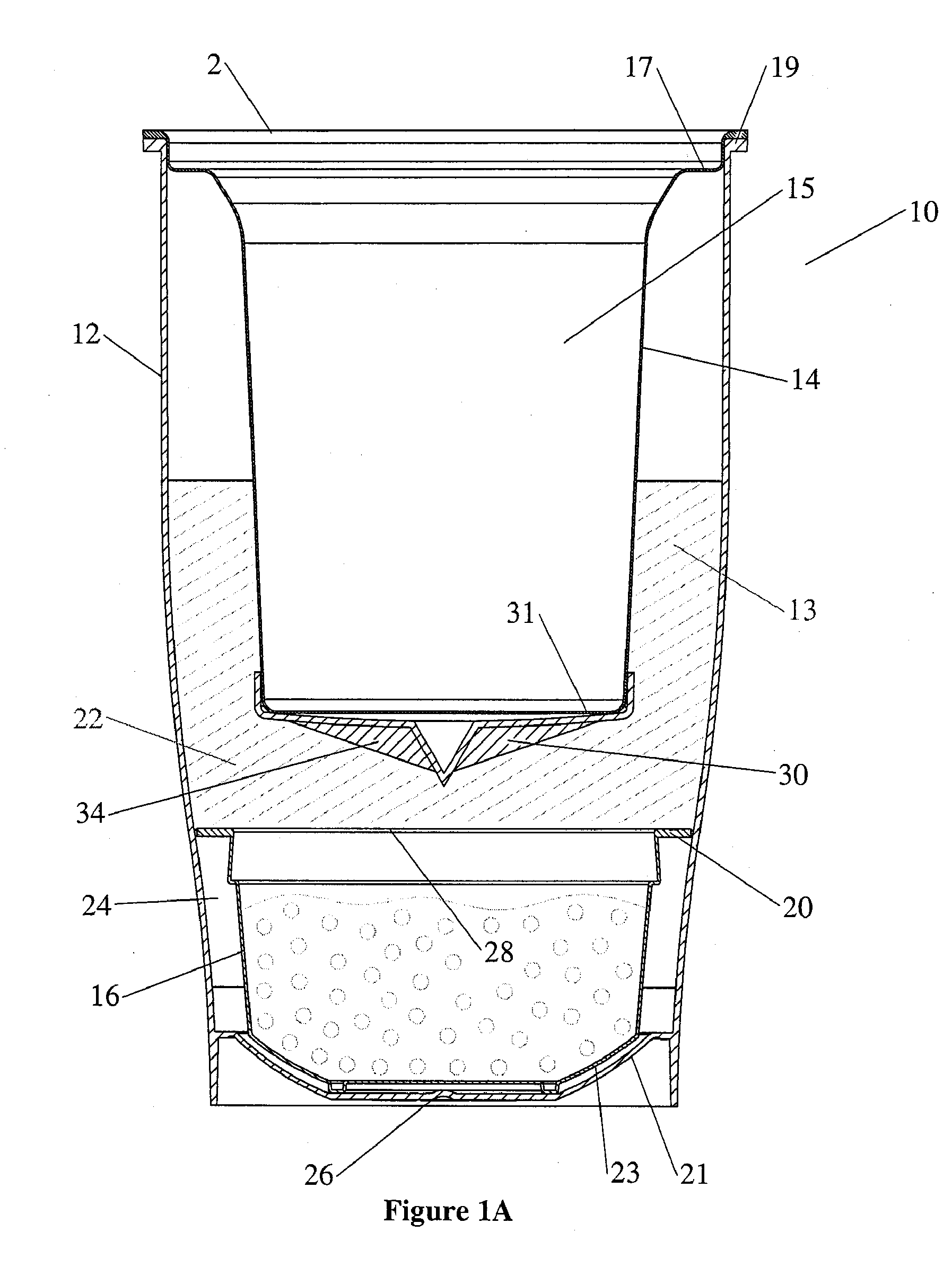
[0013] In one embodiment, the breaking device includes multiple protrusions evenly arranged through the breaking device to efficiently break the barrier and quickly release the second reactant to mix and react with the first reactant. In one example, the protrusions are multiple cone-shaped structures which taper near the barrier.
[0018] The containers according to various embodiments of the present invention are simple in design and cost efficient to manufacture.

Problems solved by technology

Numerous containers have been designed by use of the self-heating technology, but most have very limited use because the designs tend to be overly complicated in order to effect sufficient heat exchange, and as a result, the assembly and manufacturing of the containers may not be reasonably achievable from either a technical or business standpoint.
As any water present in the vicinity of the seal can adversely affect the quality of the seal, filling the lower compartment with water must be done with precision.
In addition, placing and securing the membrane is also complicated when there are many different parts of the container to be assembled.
Again, assembly of this container is quite complicated.
Because many of the container parts need to be sealed, and seals can be easily broken when the container undergoes a temperature change, the integrity of the container can be jeopardized.
The container design in this patent is complex and involve many parts to be assembled.
Most of the existing self-heating containers, as illustrated above, are quite complex in design, expensive and difficult to manufacture, and as a result, are prohibited from being widely commercialized to accommodate most consumers.

Method used


Image

  • Self-heating container
  • Self-heating container
  • Self-heating container

Examples


Embodiment Construction

[0089] The preferred embodiments of the present invention will now be described more fully hereinafter with reference to the accompanying drawings. This invention may, however, be embodied in many different forms and should not be construed as limited to the embodiments set forth herein; rather, these embodiments are provided so that this disclosure will be thorough and complete, and will fully convey the scope of the invention to those skilled in the art. Like numbers refer to like elements throughout.

[0090] Many modifications and other embodiments of the invention will come to mind to one skilled in the art to which this invention pertains having the benefit of the teachings presented in the foregoing descriptions and the associated drawings. Therefore, it is to be understood that the invention is not to be limited to the specific embodiments disclosed and that modifications and other embodiments are intended to be included within the scope of the appended claims. Although specif...


PUM


Abstract

Disclosed is various embodiments of a self-heating or self-cooling container with a number of improved features in overcoming the problems associated with existing containers, including, but not limited to, an improved breaking device designed to maximize the mixture and reaction between different reactants, an insulating lip to prevent heat loss in the heating process, a simple and efficient design of the container, and enhancements in manufacturing and assembling a self-heating or self-cooling container.

Description

CROSS-REFERENCE [0001] This application claims priority to U.S. Provisional Application Ser. No. 60 / 736,485, entitled “Self-Heating Container,” filed Nov. 14, 2005, which is herein referenced and incorporated in its entirety.BACKGROUND [0002] 1. Field of the Invention [0003] The present invention relates in general to containers, and more particularly, to improved features in a self-heating container. [0004] 2. Background of the Invention [0005] In today's on-the-go consumer society, there is increasing demand for a convenient and effective container which may be used by consumers to heat consumable products, such as coffee, tea, milk, soup, and many other types of beverage or food products, at any time and any location, without having access to any conventional heating means, such as a coffee maker, microwave, cook top, etc. The self-heating technology based on an exothermic reaction between different reagents is often used in designing such containers. Under such self-heating tech...

Claims


Application Information

Patent Timeline
Patent Type & Authority Applications(United States)
IPC IPC(8): F24J1/00F25D3/10F24J3/00F24V30/00
CPCB65D17/163B65D81/3484B65D2517/0016F24J1/00F25D5/02F25D2331/805B65D17/4011F24V30/00
Inventor FORD, JOHN M.B.LUND, DOUGLAS M.
Owner HEAT WAVE TECH
Why Eureka
Try Eureka