Heat radiating apparatus and electronic apparatus

Inactive Publication Date: 2007-06-14
FUJITSU LTD
View PDF21 Cites 51 Cited by
  • Summary
  • Abstract
  • Description
  • Claims
  • Application Information

AI Technical Summary

Benefits of technology

[0006] It is accordingly an object of the present invention to provide a heat radiating appara

Problems solved by technology

The dust filter, however, inevitably increases a resistance to the airflow at the

Method used


Image

  • Heat radiating apparatus and electronic apparatus
  • Heat radiating apparatus and electronic apparatus
  • Heat radiating apparatus and electronic apparatus

Examples


first embodiment

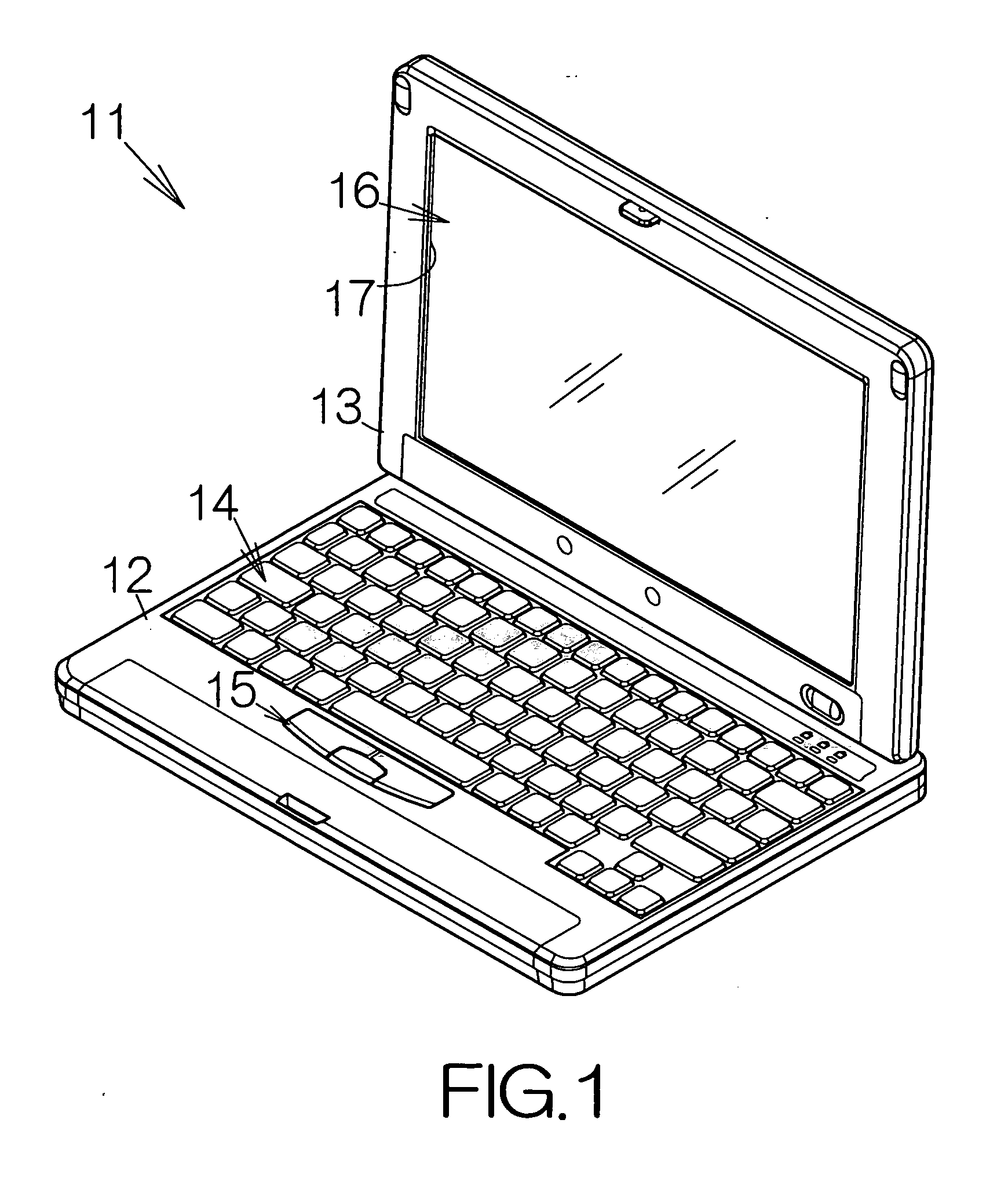
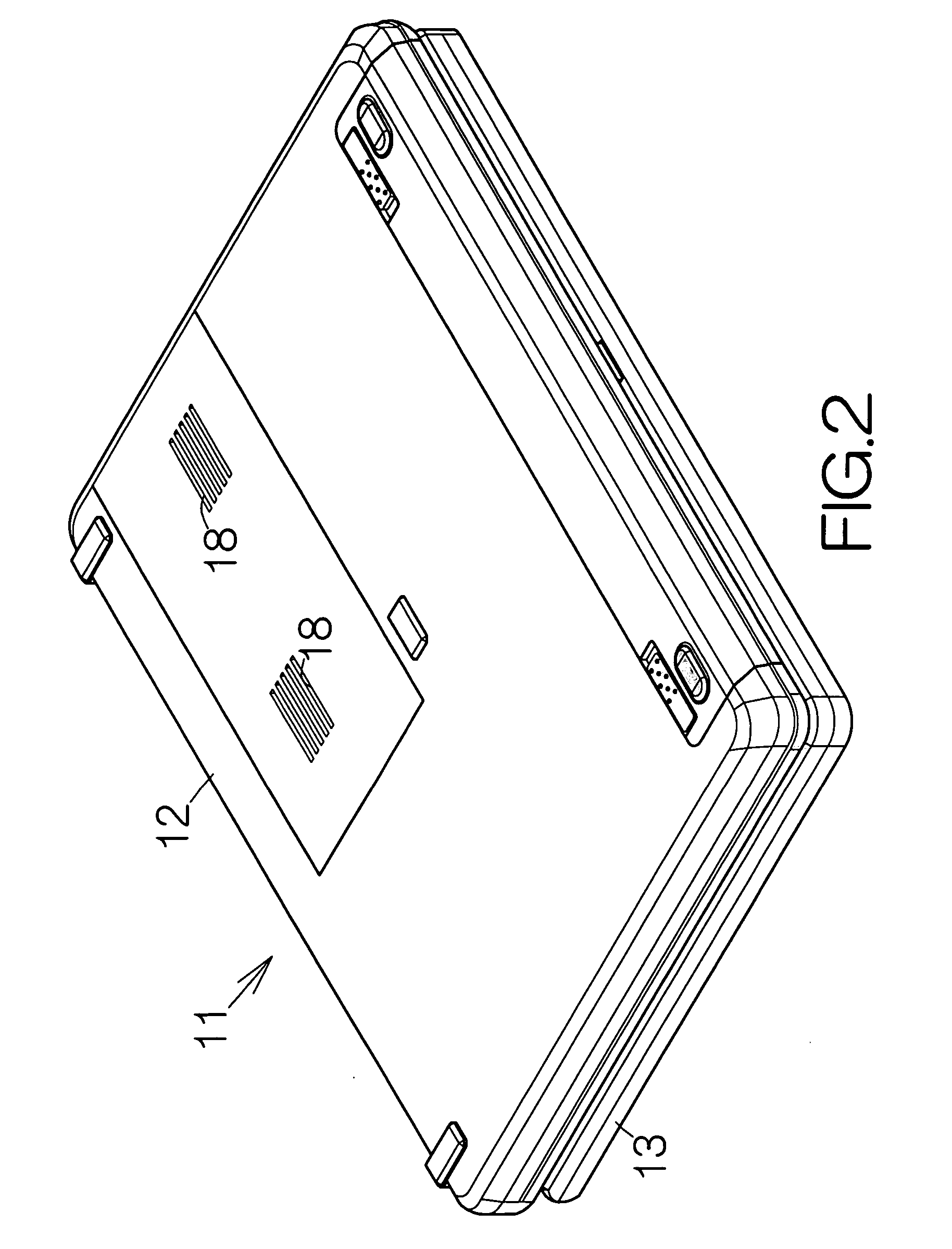
[0023] As shown in FIG. 2, a pair of air vents 18, 18 is defined in the enclosure of the main body 12. The air vents 18, 18 serve to realize air circulation between the inner and outer spaces of the enclosure. As shown in FIG. 3, an electronic component such as a central processing unit (CPU) 19 is located inside the enclosure of the main body 12 near the air vents 18, 18. The CPU 19 may be mounted on a printed circuit board 21. A heat radiating apparatus 22 according to the present invention is received on the upward surface of the CPU 19.

[0024] The heat radiating apparatus 22 includes a casing 23 serving as a heat sink. A pair of openings 24a, 24b is defined in the casing 23. The individual openings 24a, 24b serve to realize air circulation between the inner and outer spaces of the casing 23.

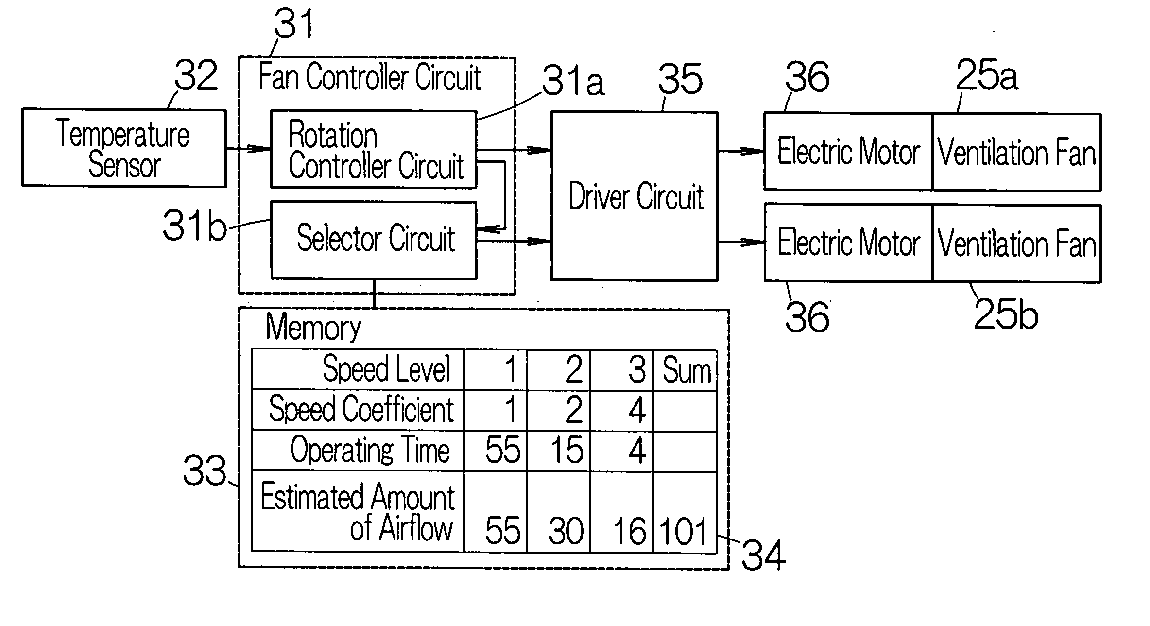
[0025] First and second ventilation fans 25a, 25b are disposed adjacent to the openings 24a, 24b, respectively. When the first ventilation fan 25a is driven to rotate, air is introduced into ...

second embodiment

[0039]FIG. 8 schematically illustrates a heat radiating apparatus 22a according to the present invention. The heat radiating apparatus 22a includes first and second ventilation fans 41a, 41b in the same manner as described above. A so-called axial flow fan is employed as the first and second ventilation fans 4la, 41b. The rotation axes of the first and second ventilation fans 41a, 41b may be aligned on a common axis. Fan blades of the second ventilation fan 41b are opposed to fan blades of the first ventilation fan 41a at a certain distance.

[0040] A heat sink 42 is interposed between the first and second ventilation fans 41a, 41b. The heat sink 42 is received on the upward surface of the CPU 19, for example. The first and second ventilation fans 41a, 41b may be coupled to the heat sink 42. The heat radiating apparatus 22a may be screwed on the printed wiring board 21. An attachment tab, not shown, may be formed integral to the heat sink 42 in this case, for example. A receiving bore...


PUM


Abstract

While one of ventilation fans operates, the other ventilation fan is at rest. Air flows from the operating ventilation fan to the ventilation fan at rest. The airflow passes through an air passage defined in a heat radiating member located between the ventilation fans. Dust cumulates at the entrance of the air passage. The other ventilation fan is then driven to operate while the operating ventilation fan is brought to rest. Airflow is generated in the reverse direction. The airflow is inverted within the air passage. The inverted airflow serves to remove the dust from the entrance of the air passage. The cumulation of the dust can thus reliably be avoided. Accordingly, no dust filter is required in the path of airflow outside the air passage. Airflow of a sufficient amount can always be maintained in the air passage.

Description

BACKGROUND OF THE INVENTION [0001] 1. Field of the Invention [0002] The present invention relates to a heat radiating apparatus comprising: at least a pair of ventilation fans; and a heat radiating member received on a heat generating object in a space between the ventilation fans. The heat radiating member serves to define an air passage extending between the ventilation fans. [0003] 2. Description of the Prior Art [0004] A heat radiating apparatus including an axial flow fan is well known as disclosed in Japanese Patent Application Publication No. 2005-150401, for example. The axial flow fan serves to introduce air into the enclosure of an electronic apparatus such as a personal computer through an opening defined in the enclosure of the electronic apparatus. The introduced air passes through an air passage defined in a heat radiating member. Heat is thus allowed to radiate from the heat radiating member in an efficient manner. [0005] A dust filter is set in the opening of the enc...

Claims


Application Information

Patent Timeline
IPC IPC(8): H01L23/467G05D23/00
CPCG05D23/19G06F1/203G06F1/206H01L23/467H01L2924/0002H01L2924/00
Inventor ASAHI, KAZUTOSHI
Owner FUJITSU LTD
Why Eureka
Try Eureka