Sealing apparatus

Inactive Publication Date: 2007-06-14
NOK CORP
View PDF7 Cites 7 Cited by
  • Summary
  • Abstract
  • Description
  • Claims
  • Application Information

AI Technical Summary

Benefits of technology

[0025] As described above, according to the present invention, the mechanical loss caused by the seal lip can be reduced while maintaining a stable sealing performance and while restraining the generation of the turn-over of the seal lip.
[0026] Hereafter, best modes for carrying out this invention will be described in detail in an exempl

Problems solved by technology

The larger this contact force is, the higher the mechanical loss will be.
However, in this case, turn-over of the seal lip is liable to be generated.
For this reaso

Method used


Image

  • Sealing apparatus
  • Sealing apparatus
  • Sealing apparatus

Examples


example 1

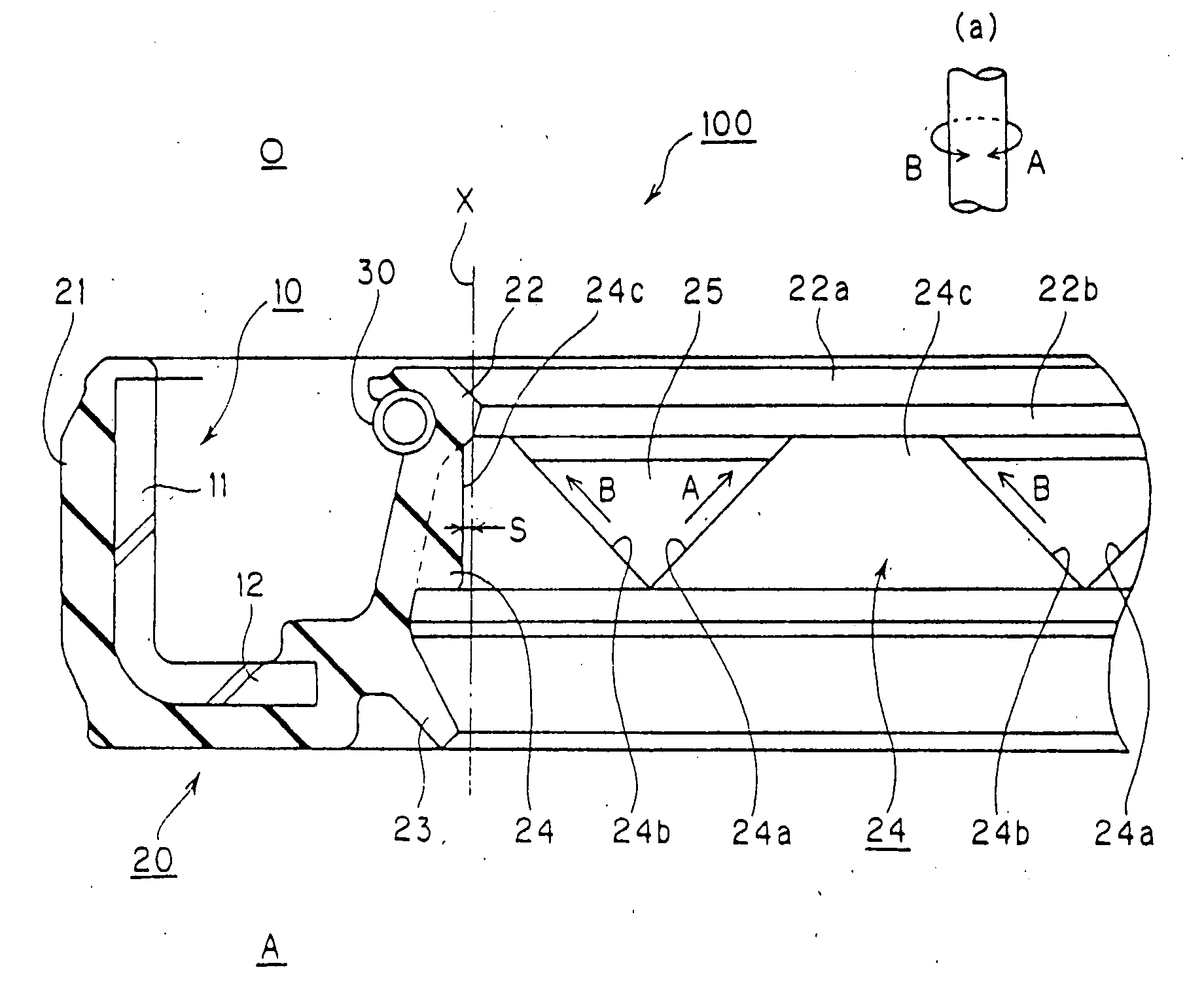
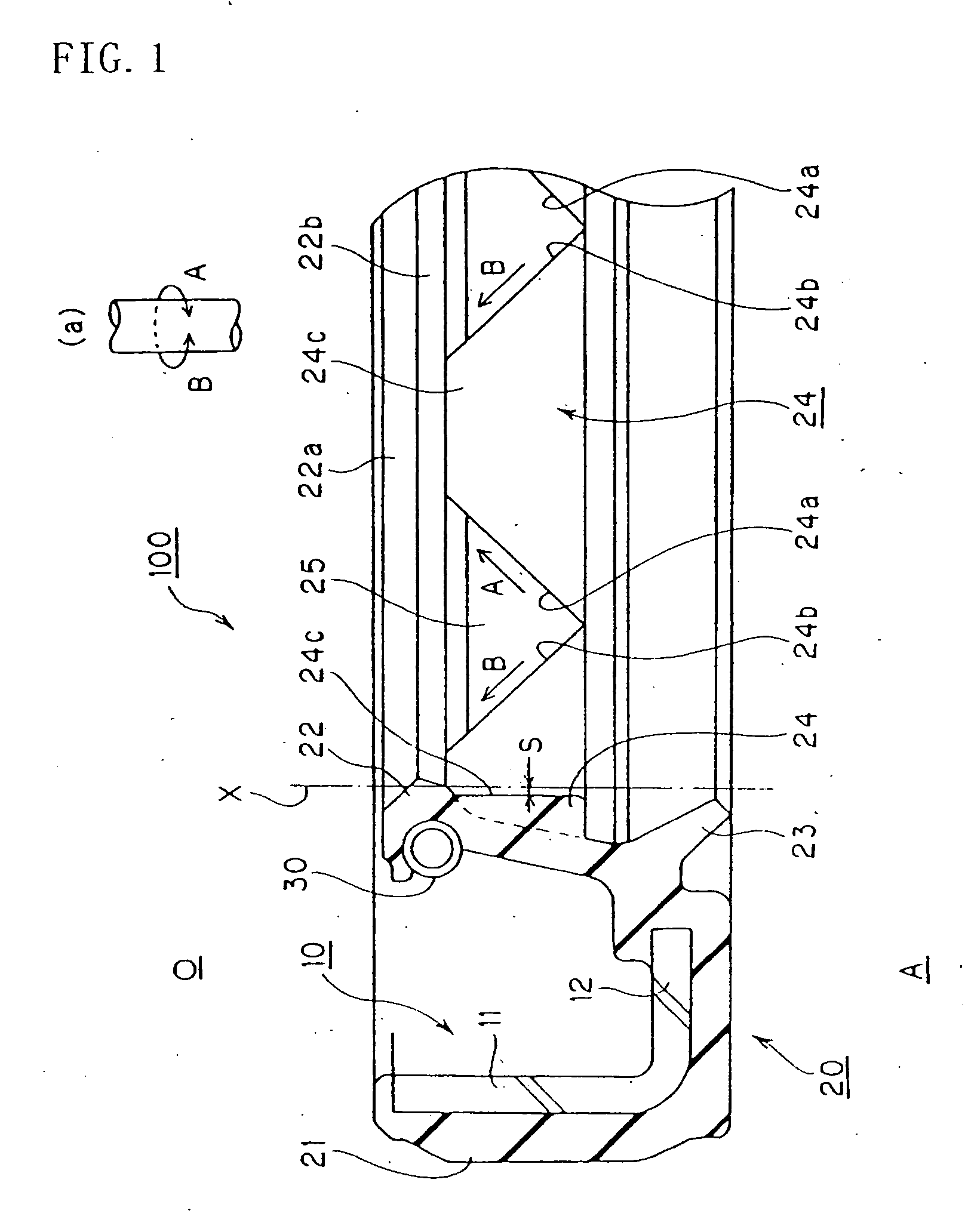
[0027] With reference to FIG. 1, a sealing apparatus according to Example 1 of the present invention will be described. FIG. 1 is a partial cross-sectional view of a sealing apparatus according to Example 1 of the present invention.

[0028] The sealing apparatus according to the Example of the present invention is used for sealing an annular gap between a shaft and a housing, not illustrated, that are relatively rotated, more specifically an annular gap between the surface of the shaft and the inner circumferential surface of the shaft hole provided in the housing into which this shaft is inserted. For example, in the case of an oil seal, an annular gap between the shaft and the shaft hole is sealed to prevent leakage of the oil.

[0029] A sealing apparatus 100 is provided with a reinforcing ring 10 having a generally L-shaped cross section and a rubber-like elastic body 20 that is baked and fixed to this reinforcing ring 10. The reinforcing ring 10 is provided with a cylindrical port...

example 2

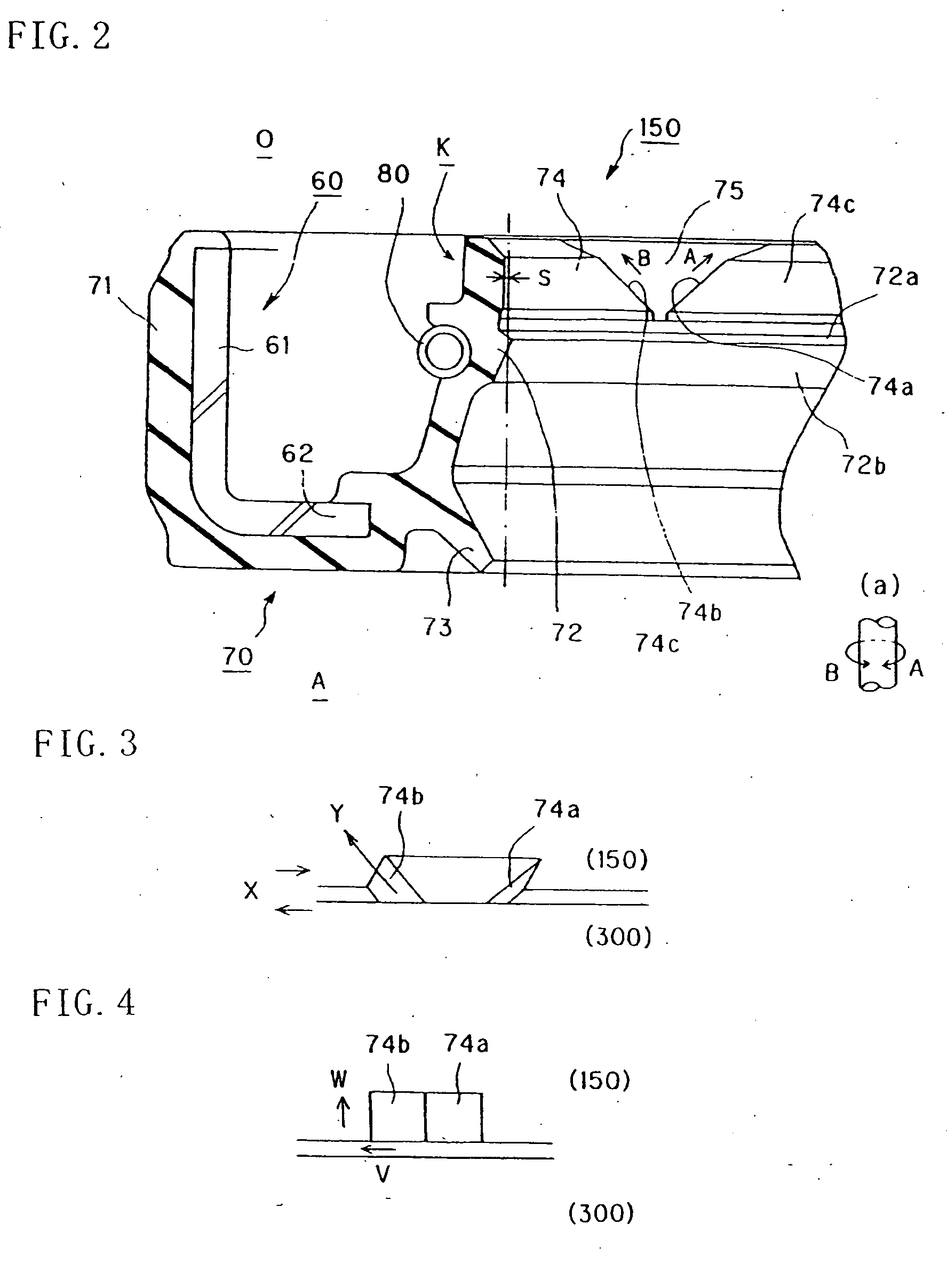
[0041] With reference to FIGS. 2 to 4, a sealing apparatus according to Example 2 of the present invention will be described. FIG. 2 is a partial cross-sectional view of the sealing apparatus according to Example 2 of the present invention. FIG. 3 is a perspective view showing an appearance of the sliding part of the seal lip and the shaft of the sealing apparatus according to Example 2 of the present invention. FIG. 4 is a front view (figure where FIG. 3 is viewed from the top) showing an appearance of the sliding part of the seal lip and the shaft of the sealing apparatus according to Example 2 of the present invention.

[0042] The sealing apparatus according to the Example of the present invention also is used for sealing an annular gap between a shaft and a housing, not illustrated, that are relatively rotated, more specifically an annular gap between the surface of the shaft and the inner circumferential surface of the shaft hole provided in the housing into which this shaft is ...


PUM


Abstract

By providing a projection 24 at the root of a seal lip 22, the mechanical loss caused by the seal lip is reduced while restraining the turn-over of the seal lip 22, while maintaining a stable sealing performance by letting the first side surface 24a or the second side surface 24b of this projection 24 exhibit a suction function of returning the fluid that has leaked from the lip tip end of the seal lip 22 to the sealing fluid side O when the shaft and the seal lip 22 are relatively rotated.

Description

TECHNICAL FIELD [0001] The present invention relates to a sealing apparatus. BACKGROUND ART [0002] Conventionally, regarding a sealing apparatus, such as an oil seal for example, that seals an annular gap between a shaft and a housing that are relatively rotated, those being provided with a seal lip that is in sliding contact with the shaft surface are general. Such a sealing apparatus will be described with reference to FIG. 5. FIG. 5 is a partial cross-sectional view of a sealing apparatus according to a related art. [0003] As illustrated, a sealing apparatus 200 according to the related art is provided with a reinforcing ring 210 and a rubber-like elastic body 220 that is baked and fixed to the reinforcing ring 210. The rubber-like elastic body 220 is provided with an outer circumference seal 221 that seals the inner circumferential surface of a shaft hole disposed in a housing not illustrated, a seal lip 222 that seals by being in sliding contact with a shaft surface not illustr...

Claims


Application Information

Patent Timeline
IPC IPC(8): F16J15/32
CPCF16J15/322F16J15/3244F16J15/32
Inventor KANDA, TSUYOSHI
Owner NOK CORP
Why Eureka
Try Eureka