Power plant coal slag conveying pipeline connector

A technology for conveying pipelines and pipe joints is applied in the field of pipe joints for coal slag conveying pipelines in power plants.

Inactive Publication Date: 2016-11-16
宁波东电电力设备制造有限公司
View PDF5 Cites 0 Cited by
  • Summary
  • Abstract
  • Description
  • Claims
  • Application Information

AI Technical Summary

Problems solved by technology

[0002] The pipe joints of the coal slag conveying pipeline in the prior art have poor assembly strength, low service life, low reliability in use, convenient disassembly when maintenance is required, and the sealing performance is not satisfactory

Method used


Image

  • Power plant coal slag conveying pipeline connector

Examples


Embodiment Construction

[0008] In order to make the technical problems, technical solutions and advantages to be solved by the present invention clearer, the following will describe in detail with reference to the drawings and specific embodiments.

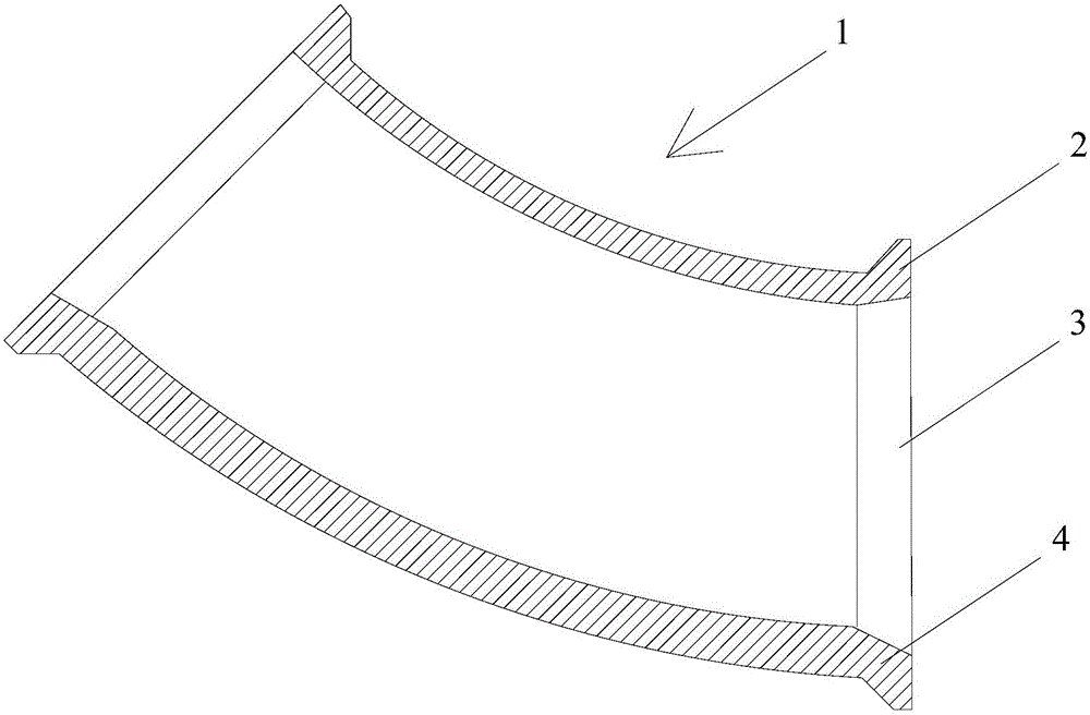
[0009] Such as figure 1 As shown, the embodiment of the present invention provides a pipe joint of a coal slag conveying pipeline in a power plant, which is composed of a pipe joint body 1 and an outer cylinder body 2. The pipe joint body has an inner sleeve part 3, and the inner sleeve part has an independent protrusion 4. There is an internal thread protrusion on the outer cylinder, and the outer cylinder forms a spiral groove on the outer peripheral surface of the pipe and advances in a spiral, and is combined with the pipe joint body in a final tightened state.

[0010] The beneficial effects of above-mentioned technical scheme of the present invention are as follows:

[0011] In the above solution, the present invention can fully withstand the pull...


PUM


Abstract

The invention discloses a power plant coal slag conveying pipeline connector which is composed of a pipe connector body and an outer cylinder body. The pipe connector body is provided with an inner insertion cylinder part which is provided with an independent protruding bar. The outer cylinder body is provided with an inner thread protruding bar. A spiral groove is formed in the outer circumferential face of a pipeline by the outer cylinder and advances in a spiral manner, and the spiral groove is combined with the pipe connector body in a final fastened state. In the above scheme, the drawing force of the pipeline can be tolerated sufficiently in the situation that the number of parts is relatively small, and the stable sealing performance can be achieved. In addition, connection work can be simply conducted with commonly-used work tools such as a wrench.

Description

technical field [0001] The invention relates to the technical field of mining machinery, in particular to a pipe joint of a coal slag conveying pipeline in a power plant. Background technique [0002] The pipe joints of the coal slag conveying pipelines in the prior art have poor assembly strength, low service life, low reliability in use, convenient disassembly when maintenance is required, and unsatisfactory sealing performance. Contents of the invention [0003] The technical problem to be solved by the present invention is to provide a pipe joint for coal slag conveying pipeline in a power plant to solve the above technical problem. [0004] In order to solve the above technical problems, an embodiment of the present invention provides a pipe joint of a coal slag conveying pipeline in a power plant, which is composed of a pipe joint body and an outer cylinder. There is an internal thread protrusion on the outer cylinder, and the outer cylinder forms a spiral groove on...

Claims


Application Information

Patent Timeline
IPC IPC(8): F16L43/00
CPCF16L43/00
Inventor 王朝晖
Owner 宁波东电电力设备制造有限公司
Why Eureka
Try Eureka