Electromagnetic drive unit

An electromagnetic drive and yoke technology, which is applied in the direction of electromagnets, electrical components, engine components, etc., can solve problems such as coil short circuit and coil disconnection, achieve improved water resistance, excellent water resistance, and suppress short circuit of solenoid components Effect

Active Publication Date: 2013-04-24
HITACHI CONSTR MASCH CO LTD
View PDF8 Cites 5 Cited by
  • Summary
  • Abstract
  • Description
  • Claims
  • Application Information

AI Technical Summary

Problems solved by technology

Here, the solenoid assembly is generally configured such that the bobbin in the state where the coil is wound is covered from the outside by the outer mold, but if the bobbin is immersed in water from a position where the bobbin and the outer mold are not completely in close contact, the There are cases where the coil is short-circuited, or the coil is disconnected due to corrosion, etc.

Method used


Image

  • Electromagnetic drive unit
  • Electromagnetic drive unit
  • Electromagnetic drive unit

Examples


Embodiment Construction

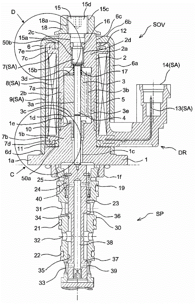
[0036] Below, refer to Figure 1 to Figure 5 , and an embodiment example of the present invention will be described. Such as figure 1 As shown, the electromagnetic drive unit DR according to the embodiment of the present invention is connected to a directional control valve unit SP as a driven device through one end side, and is used as a solenoid valve SOV. The solenoid valve SOV is a 3-port 2-position directional control valve that operates electromagnetically. Valve / throttle valve control, AT car clutch unit, forward / reverse switching clutch control, etc.

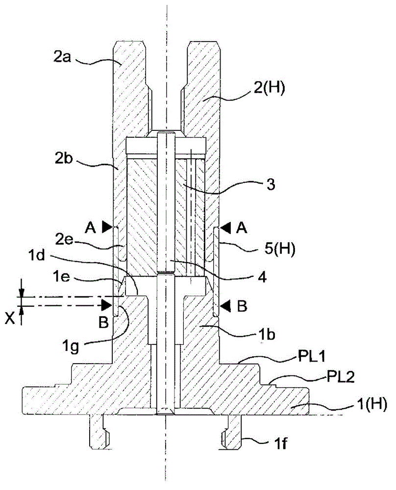
[0037] The electromagnetic drive unit DR has an inner housing H formed of a stator 1, a ring (cylindrical member) 5, and a yoke 2, wherein the stator 1 is made of a magnetic material, the ring 5 is made of a non-magnetic material, and the yoke 2 is made of a magnetic material. The stator 1, the ring 5, and the yoke 2 constituting the inner housing H are arranged coaxially with each other. In addition, the solenoid ...


PUM


Abstract

To provide an electromagnetic drive unit that ensures stabilized sealing performance. [Solution] An electromagnetic drive unit according to the present invention includes an inner housing (H) that encloses the plunger (3), a solenoid assembly (SA) that moves the plunger in an axial direction, and a casing (6) that covers the solenoid assembly. A first annular space (50a) for mounting a first sealing member (11) in an annular shape is formed between the inner housing and the solenoid assembly. When the first sealing member has an outer diameter OD1, the first annular space (50a) forms approximately a rectangular shape where any cross-sectional surface of the space satisfies a relation expressed by a distance LA1 < the outer diameter OD1 < a distance LB1. Respective positions where a first surface (SF1) and a second surface (SF2) are in close contact with the first sealing member are formed at a third surface (SF3) side with respect to an intersection point where the second surface (SF2) and a fourth surface (SF4) cross one another in the axial direction.

Description

technical field [0001] The present invention relates to an electromagnetic drive unit, and more particularly, to a sealing structure of an electromagnetic drive unit in the form of a solenoid assembly suitable for mounting on the outside of an inner case with a built-in plunger. Background technique [0002] Generally, the electromagnetic drive unit is configured to move the plunger in the axial direction by controlling the power supply to the solenoid unit. Here, the solenoid assembly is usually configured such that the bobbin in the state where the coil is wound is covered from the outside by the outer mold. The coil may be short-circuited or the coil may be disconnected due to corrosion. In order to prevent such a problem, conventionally, a structure is known in which the solenoid assembly is covered with an outer cover, and a sealing member such as an O-ring is installed in a groove between the outer cover and the solenoid assembly, so that the outer cover and the solen...

Claims


Application Information

Patent Timeline
IPC IPC(8): H01F7/126F16K31/06H01F7/06H01F7/16
CPCH01F7/126H01F7/1607F16K31/06H01F7/06H01F7/16
Inventor 平野樱子吉本光宏伊东英明高尾昌希
Owner HITACHI CONSTR MASCH CO LTD
Why Eureka
Try Eureka