
Recording apparatus

Inactive Publication Date: 2007-06-14
CANON KK
View PDF8 Cites 3 Cited by
  • Summary
  • Abstract
  • Description
  • Claims
  • Application Information

AI Technical Summary

Benefits of technology

[0011] The present invention is directed to a recording apparatus provided with a display device which has a compact and inexpensive structure and is excellent in visibility.

Problems solved by technology

As a result, it is not possible to achieve both the improvement of the visibility and slimming-down of the display device at the same time.
However, in the structure illustrated in FIG. 11, because the plurality of light emitting diodes 910 are necessary in one display part 810, the cost and the power consumption of the device increase.
For example, in a battery-operated printer, the increase of the power consumption shortens operating time of the printer.

Method used


Image

  • Recording apparatus
  • Recording apparatus
  • Recording apparatus

Examples


Embodiment Construction

[0032] Various exemplary embodiments, features, and aspects of the invention will now herein be described in detail below with reference to the drawings.

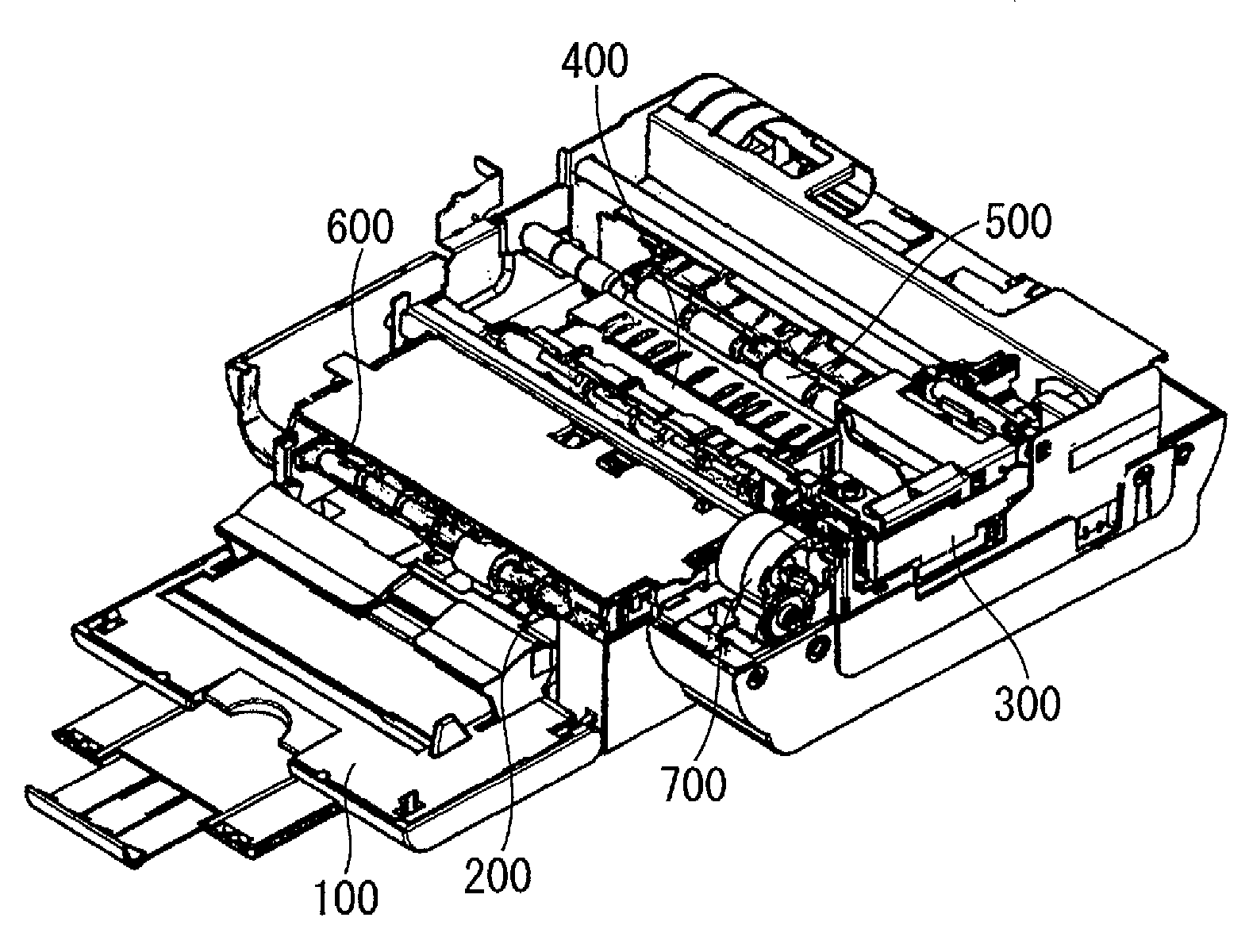
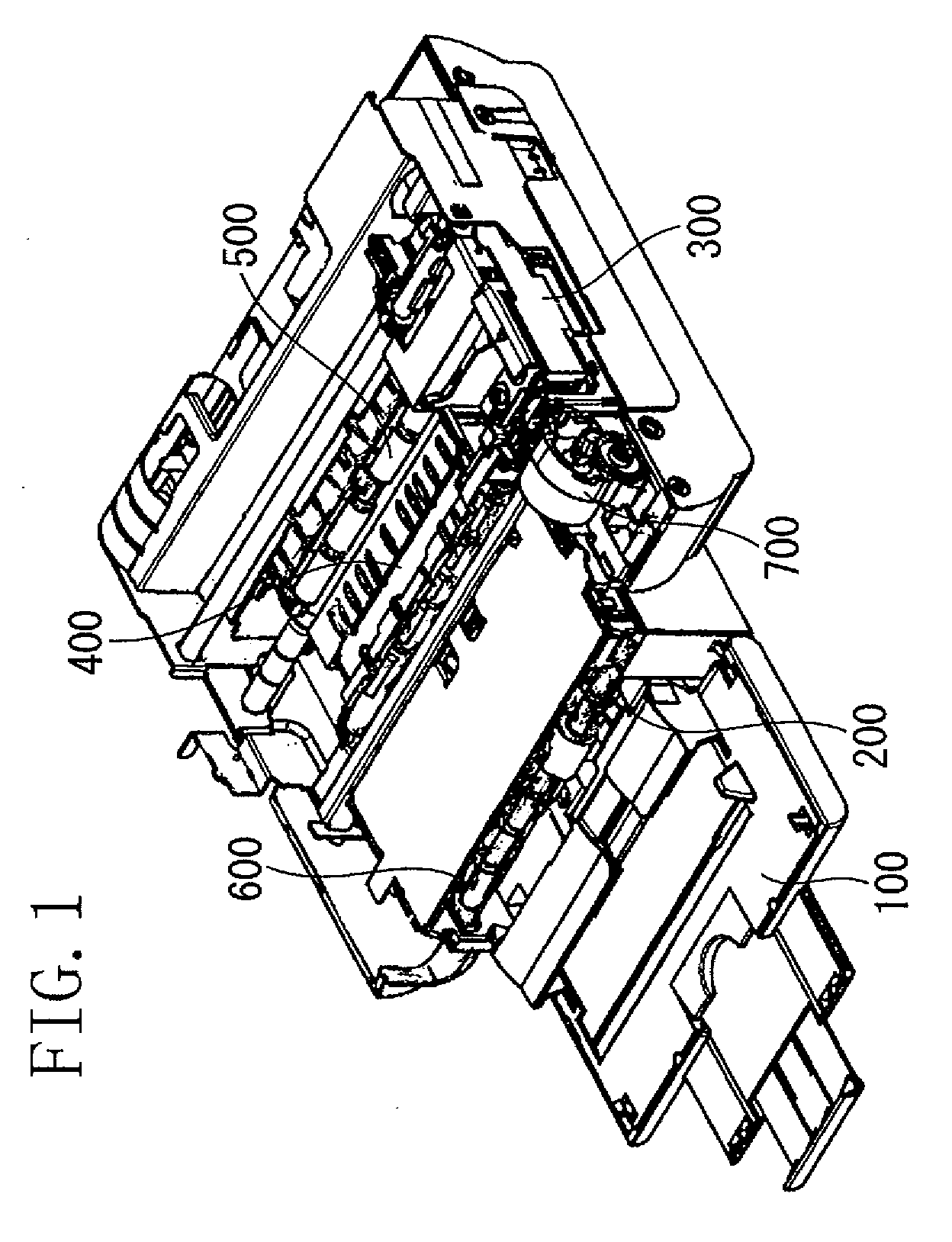
[0033]FIG. 1 is a perspective view illustrating an example internal structure of a recording apparatus according to a first exemplary embodiment of the present invention. In this exemplary embodiment, an inkjet recording apparatus is described, as an example, which forms an image by discharging ink from a recording head onto a recording medium such as recording paper or film based on image information. In FIG. 1, the recording apparatus includes a feeding / discharging tray 100, a separation / feeding / discharging part 200, a recording unit 300, an image forming part 400, a first roller 500, a second roller 600 and a drive transmission 700.

[0034] The feeding / discharging tray 100 includes a stack unit on which a recording medium recorded by the recording unit 300 is stacked and placed as well as a plurality of unrecorded recording media...


PUM


Abstract

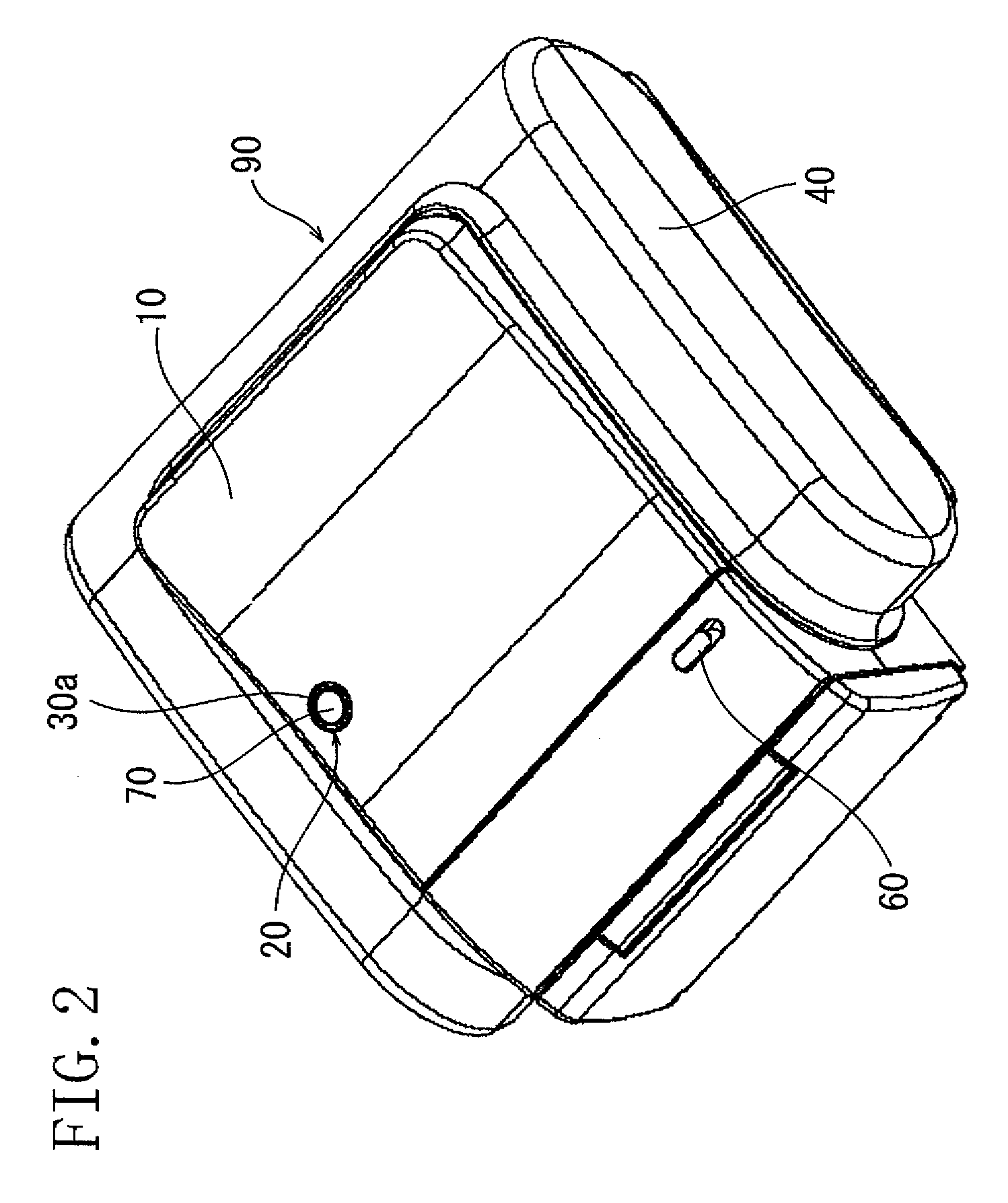
A device is provided which includes a substrate arranged in an interior thereof having a light emitting element positioned on an upper surface of the substrate; and a push button assembly disposed in an exterior structure of the device above the emitting element. The button assembly includes a cylindrical light guide for receiving / guiding light to an annular display part disposed on an upper portion of the light guide. The light guide is further defined by a lower end, and an inner and outer wall. A portion of the outer wall proximate to the lower end has a tapered surface portion. A push button part is movably disposed within the light guide. The emitting element is positioned coincident with a center axis of the light guide. Light emitted by the element is received by the light guide, reflected by the tapered portion, and guided towards the display part.

Description

BACKGROUND OF THE INVENTION [0001] 1. Field of the Invention [0002] The present invention relates to a recording apparatus, and more particularly, relates to a structure of an operation key which is provided in an exterior of the recording apparatus, and has a display part and an operation part. [0003] 2. Description of the Related Art [0004] In information processing apparatuses, such as office computers, personal computers, and / or a word processors, display devices for displaying various information about a status of the apparatus have been conventionally used. Also in image recording apparatuses or image reading apparatuses such as printers, copying machines, printing devices, facsimile machines, and / or scanners, similar display devices have been used. [0005] The display device is generally arranged in an exterior of the device where the display device is easily viewed. In recent years, as the information apparatuses are personalized, the size of the devices has become miniaturiz...

Claims


Application Information

Patent Timeline
IPC IPC(8): G01D11/28
CPCH01H13/023H01H2219/0622
Inventor ASAI, YASUYUKI
Owner CANON KK
Learn More