Hybrid drive device

a drive device and hybrid technology, applied in hybrid vehicles, electrical control, vehicle sub-unit features, etc., can solve the problems of reverse rotation output of the internal combustion engine, and achieve the effect of reducing the cost of electric oil pumps, and compact and inexpensive structures

Inactive Publication Date: 2014-07-10
AISIN AW CO LTD
View PDF3 Cites 3 Cited by
  • Summary
  • Abstract
  • Description
  • Claims
  • Application Information

AI Technical Summary

Benefits of technology

[0005]If all the hydraulic pressure required for the continuously variable transmission is to be provided by an electric oil pump, it is necessary to adopt a large and expensive electric oil pump, which is unfavorable. Therefore, a mechanical oil pump driven in conjunction with the internal combustion engine is provided so that the mechanical oil pump outputs a belt holding pressure that is enough to even resist the maximum output torque of the internal combustion engine during forward travel. This makes the electric oil pump auxiliary, and allows adopting a compact and inexpensive structure as a whole.
[0006]If reverse travel (EV travel) is to be performed using output of the motor as discussed above, a belt holding pressure that can resist the maximum output of the motor is required. For EV travel in which the internal combustion engine is stopped, however, it is necessary that all the hydraulic pressure (belt holding pressure) should be provided by the electric oil pump, which hinders downsizing and cost reduction of the electric oil pump.
[0007]It is therefore an object of the present invention to provide a hybrid drive device that enables downsizing and cost reduction of an electric oil pump by reducing the size of the electric oil pump by reducing a required hydraulic pressure to he output from the electric oil pump during reverse travel in which a rotary electric machine outputs reverse rotation to rotate wheels rearward.

Problems solved by technology

In general, a continuously variable transmission of a belt type or the like that varies the speed of rotation of an internal combustion, engine includes a forward / reverse travel switching device that enables reverse travel by reversing input rotation, because it is difficult for the internal combustion engine to output reverse rotation.

Method used


Image

  • Hybrid drive device
  • Hybrid drive device
  • Hybrid drive device

Examples


Embodiment Construction

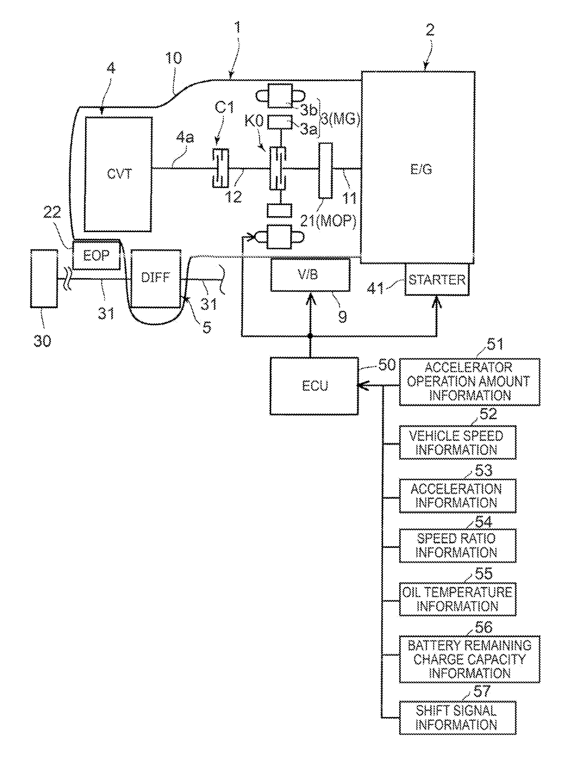
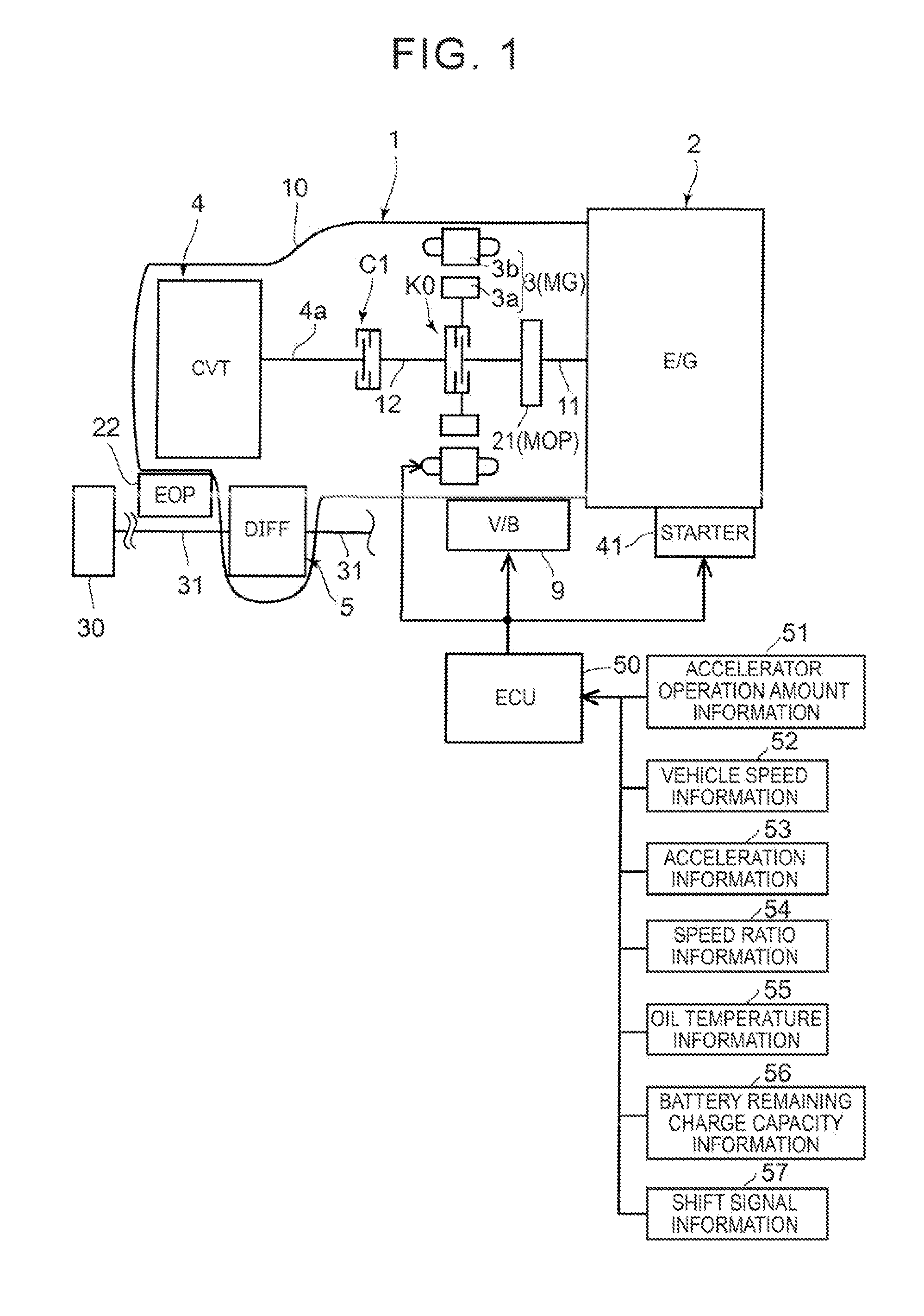
[0030]An embodiment of the present invention will be described below with reference to FIGS. 1 to 5. First, a schematic configuration of a hybrid drive device to which the present invention can be applied and a drive system of a vehicle on which the hybrid drive device is mounted will be described with reference to FIG. 1.

[0031]As illustrated in FIG. 1, a vehicle of an FF (front engine from drive) type includes an internal combustion engine (E / G) 2 mounted with an output shaft (crankshaft) (not illustrated) disposed transversely with respect to the travel direction of the vehicle. An input shaft (first shaft) 11 of a hybrid drive device 1 according to the present invention is drivably coupled to the output shaft of the internal combustion engine 2. Left and right axes 31, 31 for front wheels are drivably coupled to a differential device (DIFF) 5 of the hybrid drive device 1. Left and right front wheels 30 are connected to the left and right axes 31, 31. A starter (STARTER) 41 for st...


PUM


Abstract

A hybrid drive having a hydraulic control device capable of hydraulically controlling a first clutch, a second clutch, and a continuously variable transmission using a hydraulic pressure generated by at least one of a mechanical oil pump and an electric oil pump. A control section is configured to execute a mechanical oil pump drive mode in which a command to start an internal combustion engine is provided to drive the mechanical oil pump via a first shaft using output rotation of the internal combustion engine during reverse travel in which reverse rotation is output from the rotary electric machine to rotate wheels in reverse via the second shaft, the second clutch, and the continuously variable transmission with the first clutch disengaged and with the second clutch engaged by providing a command to the hydraulic control device.

Description

FIELD[0001]The present invention relates to a hybrid drive device mounted on a vehicle or the like, and in particulars to a hybrid drive device that includes a mechanical oil pump driven in conjunction with an internal combustion engine and an electric oil pump driven independently of the mechanical oil pump and that hydraulically controls a continuously variable transmission on the basis of a hydraulic pressure from the oil pumps.BACKGROUND ART[0002]In recent years, in order to improve the fuel efficiency of vehicles, there are proposed a variety of hybrid drive devices mounted on a vehicle or the like. Among others, there are proposed a hybrid drive device with a simple structure in which one motor is disposed between an internal combustion engine and a continuously variable transmission (see Patent Document 1). In general, a continuously variable transmission of a belt type or the like that varies the speed of rotation of an internal combustion, engine includes a forward / reverse ...

Claims


Application Information

Patent Timeline
Patent Type & Authority Applications(United States)
IPC IPC(8): F02D41/32B60L50/16
CPCF02D41/32B60K6/387B60K6/48B60K6/543B60L15/20B60L2240/12B60L2240/423B60L2240/443B60L50/16Y02T10/64Y02T10/7072B60K2006/541B60L2240/445B60L2240/486B60L2250/26B60W10/02B60W10/30B60W30/18036B60Y2200/92B60Y2400/72B60L58/12F02D29/02F16H61/0025F16H61/0031Y02T10/62Y02T10/70Y02T10/72
Inventor OOTSUKI, TAKESHI
Owner AISIN AW CO LTD
Why Eureka
Try Eureka