Image pickup lens and image pickup apparatus

a pickup apparatus and image technology, applied in the field of image pickup lenses and image pickup apparatuses, can solve the problems of difficult conventional lens systems to realize both a lenses cannot meet the recent demand, and distortion increases rapidly and significantly on the negative side, so as to achieve compact and inexpensive structure, wide angle of view, and high optical performance.

Active Publication Date: 2013-12-17
TIANJIN OFILM OPTO ELECTRONICS CO LTD
View PDF9 Cites 1 Cited by
  • Summary
  • Abstract
  • Description
  • Claims
  • Application Information

AI Technical Summary

Benefits of technology

[0035]According to the image pickup lens of the present invention, a compact and inexpensive lens system, yet having a wide angle of view and high optical performance, may be provided in a four lens system by appropriately selecting the power and shape of each lens and disposing the aperture at an appropriate position.
[0036]The image pickup apparatus of the present invention includes the image pickup lens of the present invention, so that the apparatus may be structured compactly and inexpensively, yet allowing wide angle imaging and acquisition of high quality images.

Problems solved by technology

It has been difficult, however, for conventional lens systems to realize both a compact and inexpensive structure and to satisfy the recent demands of wider angle and high optical performance.
Thus, the lenses can not comply with the recent demand of wider angles of view over 180°.
The lens described in Patent Document 4 has an F-number of 2.5 to 2.8 with a total angle of view over 180°, but when a projection system with an ideal image height of 2×f×tan (φ / 2), wherein f is the focal length of the entire system and φ is the half angle of view, is employed, the system has a disadvantage that the distortion increases rapidly and significantly on the negative side when the half angle of view exceeds 80° and an image in the outermost peripheral portion becomes small.

Method used


Image

  • Image pickup lens and image pickup apparatus
  • Image pickup lens and image pickup apparatus
  • Image pickup lens and image pickup apparatus

Examples


Embodiment Construction

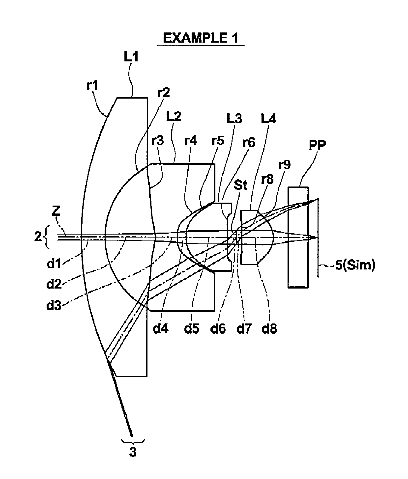
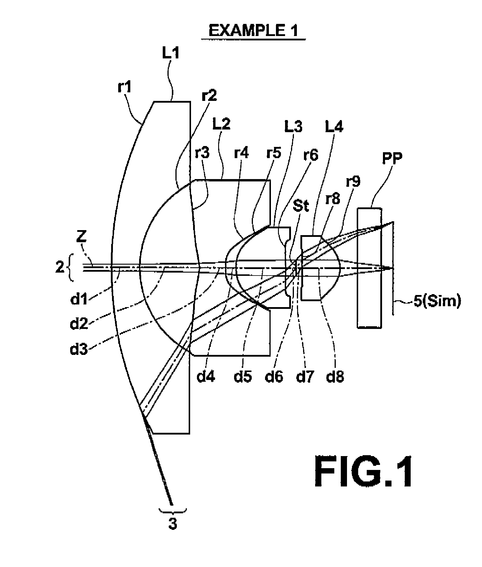
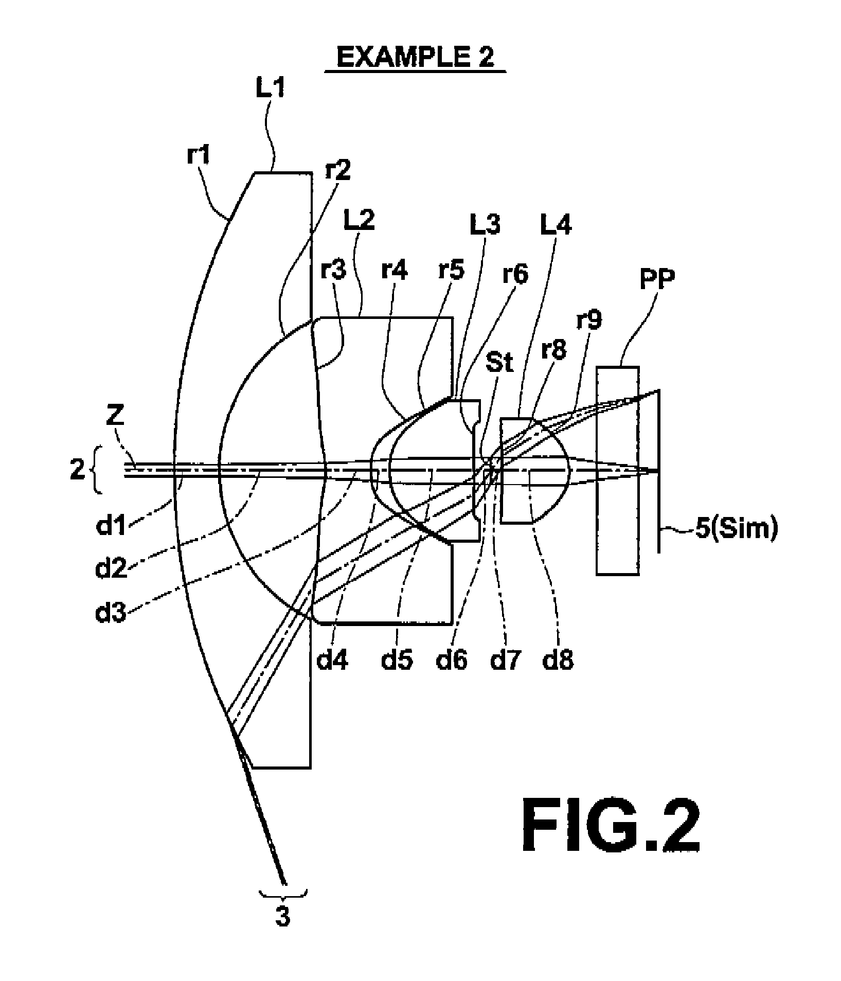
[0054]Hereinafter, embodiments of the present invention will be described in detail with reference to the accompanying drawings. FIGS. 1 to 8 are cross-sectional views of image pickup lenses according to embodiments of the present invention, illustrating example structures thereof. The lenses shown in FIGS. 1 to 8 correspond respectively to lenses of Examples 1 to 8, to be described later. Basic structures of examples shown in FIGS. 1 to 8 are identical and are illustrated in the same manner. Therefore, description of image pickup lenses according to embodiments of the present invention will be made here with reference mainly to FIG. 1.

[0055]The image pickup lens shown in FIG. 1 is a lens system having four lenses disposed from the object side in the order of first lens L1, second lens L2, third lens L3, and fourth lens L4 along optical axis Z. Aperture stop St is disposed between the third lens L3 and fourth lens L4. Disposition of aperture stop St between the third lens L3 and fou...


PUM


Abstract

An image pickup lens having the following disposed from an object side in the order listed below: a first lens having a negative meniscus shape with a concave surface on an image side, a second lens having a negative meniscus shape with a concave surface on the object side adjacent to an optical axis, a third positive lens having a convex surface on the image side adjacent to the optical axis, an aperture, and a fourth lens having a bi-convex shape adjacent to the optical axis. Each of the second, third, and fourth lenses has an aspherical surface on each side.

Description

BACKGROUND OF THE INVENTION[0001]1. Field of the Invention[0002]The present invention relates to an image pickup lens and an image pickup apparatus, and more particularly to a wide angle image pickup lens which is appropriate for use with a vehicle camera, a surveillance camera, or the like which includes an image sensor, such as a CCD (charge coupled device) or a CMOS (complementary metal oxide semiconductor), and an image pickup apparatus having the image pickup lens.[0003]2. Description of the Related Art[0004]Image sensors, such as CCD or CMOS devices, have recently been greatly downsized with increased pixel counts. Consequently, image pickup devices themselves and image pickup lenses to be mounted on the devices are also required to be reduced in size and weight. In the mean time, image pickup lenses used in vehicle cameras and surveillance cameras are required to have a high weather resistance in addition to a wide angle of view and high optical performance to secure a favora...

Claims


Application Information

Patent Timeline
Patent Type & Authority Patents(United States)
IPC IPC(8): G02B3/02G02B13/18
CPCG02B13/04G02B13/18
Inventor YAMAKAWA, HIROMITSU
Owner TIANJIN OFILM OPTO ELECTRONICS CO LTD
Why Eureka
Try Eureka