Apparatus and method for determining transmit/receive antenna in communication system using multiple antennas

a communication system and antenna technology, applied in the field of antennas and antenna methods, can solve the problems of loss of information, efficiency and reliability of data transmission over a channel, wireless channel environment existing in a mobile communication system, etc., and achieve the effect of reducing system complexity, optimizing antenna selection, and reducing the amount of information for antenna selection fed back between a transmitter and a receiver

Inactive Publication Date: 2007-06-14
SAMSUNG ELECTRONICS CO LTD
View PDF6 Cites 72 Cited by
  • Summary
  • Abstract
  • Description
  • Claims
  • Application Information

AI Technical Summary

Benefits of technology

[0022] An object of the present invention is to provide an apparatus and a method for determining a transmit / receive antenna in a communication system using multiple antennas, by which the amount of information for antenna selection fed back between a transmitter and a receiver decreases.
[0023] An object of the present invention is to provide an apparatus and a method for determining a transmit / receive antenna in a communication system using multiple antennas, by which system complexity is reduced.

Problems solved by technology

A fundamental issue in communication is the efficiency and reliability with which data is transmitted over a channel.
However, unlike the wire channel environment, the wireless channel environment existing in a mobile communication system is subject to inevitable errors due to several factors such as multipath interference, shadowing, propagation attenuation, time-varying noise, interference and fading, all of which result in a loss of information.
The information loss distorts actual transmission signals, causing deterioration in the overall performance of the mobile communication system.
However, channels are established by the respective antennas in the communication system, and are characteristic of the wireless channel and thus do not exhibit the same performance for all the antennas.
However, when a system is implemented such that the complete channel information is transmitted / received as stated above, system complexity and the amount of data transmitted / received between the transmitter and the receiver problematically increases.
Thus, when using the partial channel information, the system complexity and the amount of data transmitted / received between the transmitter and the receiver decreases as compared with the aforementioned first transmit antenna selection method.
However, when the partial channel information is fed back, the overall system performance deteriorates, because imperfect channel knowledge prevent the transmitter from choosing appropriate transmit antennas.
Since the total number of cases is ascertained in the exhaustive search technique, a very high system complexity is incurred.
However,, in proportion to the reduction in system complexity, it becomes difficult to optimize the receive antenna selection.
This method enables complexity to be distributed over transmit and receive antennas, but a large amount of feedback information is required for antenna selection, and also joint optimization is difficult.
This method is problematic in that it also requires a large amount of information to be fed back to a transmitter, and selecting a receive antenna on a transmit antenna side is somewhat useless.

Method used


Image

  • Apparatus and method for determining transmit/receive antenna in communication system using multiple antennas
  • Apparatus and method for determining transmit/receive antenna in communication system using multiple antennas
  • Apparatus and method for determining transmit/receive antenna in communication system using multiple antennas

Examples


first embodiment

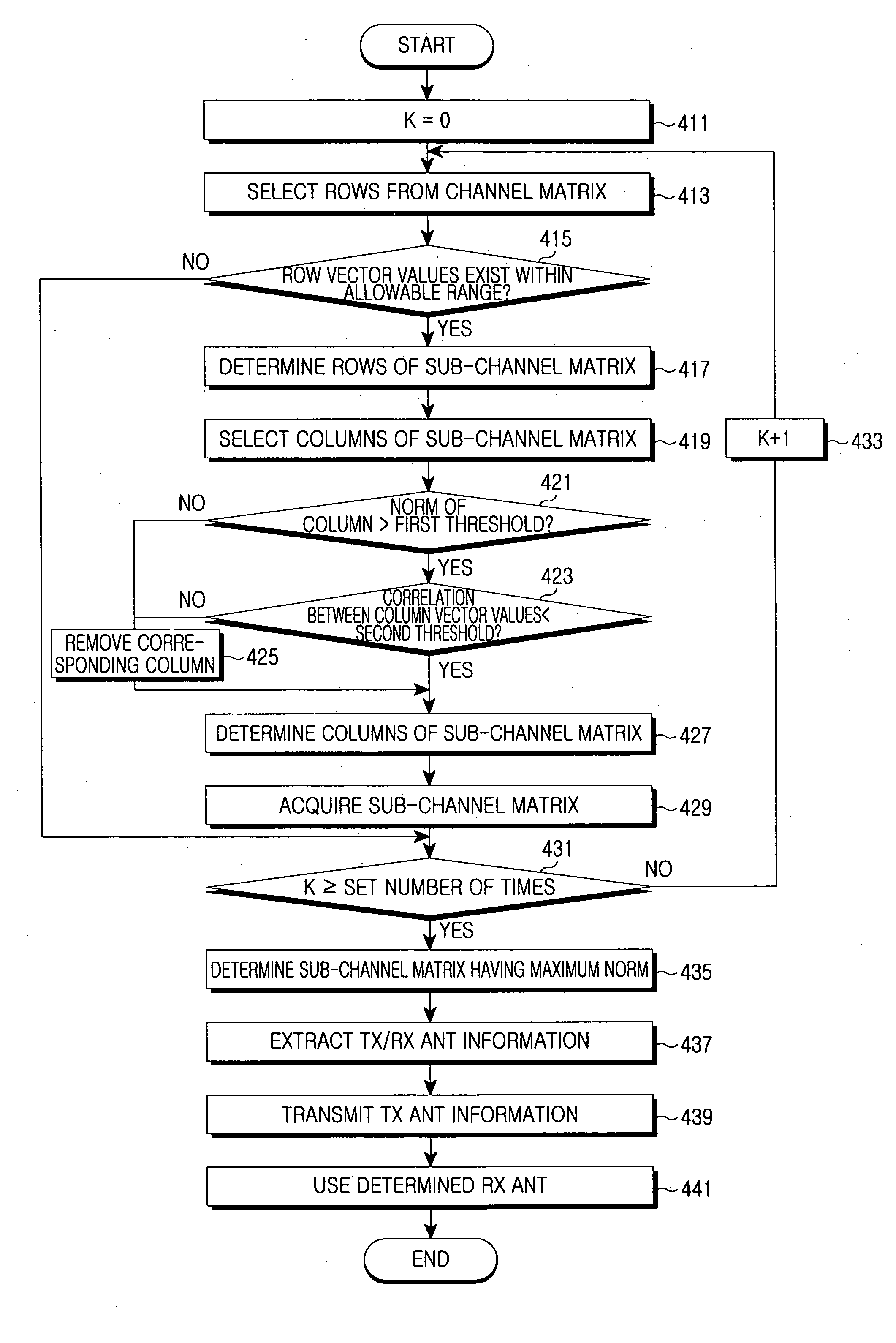
[0085]FIG. 4 is a flowchart illustrating an operational procedure of determining a Rx ANT in a receiver by using Rx ANT information according to the present invention.

[0086] Referring to FIG. 4, a receiver sets a value of K, for preventing performance deterioration, to 0 in step 411, and proceeds to step 413. Since the receiver uses probability to acquire a sub-channel matrix, performance deterioration may occur. Thus, a sub-channel matrix is iteratively generated the number of times corresponding to a value of K.

[0087] The receiver selects rows of a sub-channel matrix from a channel matrix, using Equation (5), in step 413, and proceeds to step 415. The receiver determines in step 415 whether a vector value of each selected row is within an allowable range. The allowable range is set such that rows having vector values near to zero (0) are excluded from the selected rows. If the norm of any row vector has a value near 0, then an antenna channel state in the corresponding row vector...

second embodiment

[0102]FIG. 5 is a flowchart illustrating an operational procedure of determining a Rx ANT in a receiver by using Rx ANT information according to the present invention.

[0103] Referring to FIG. 5, a receiver sets a value of K, for preventing performance deterioration, to 0 in step 511, and proceeds to step 513. Since the receiver uses probability to acquire a sub-channel matrix, performance deterioration may occur. Thus, a sub-channel matrix is iteratively generated the number of times corresponding to a value of K.

[0104] The receiver selects rows of a sub-channel matrix from a channel matrix using Equation (5), in step 513, and proceeds to step 515. The receiver determines in step 515 whether a vector value of each selected row is within an allowable range. The allowable range is set such that rows having vector values near to zero (0) are excluded from the selected rows. If the norm of any row vector has a value near to 0, then an antenna channel state in the corresponding row vect...


PUM


Abstract

Disclosed are an apparatus and a method for determining a transmit / receive antenna in a Multiple Input Multiple Output (MIMO) communication system. At least one sub-channel matrix including transmit antenna information and receive antenna information is generated. From the at least one sub-channel matrix, a sub-channel matrix having a maximum value Frobenius norm is determined. The transmit and receive antenna information are then extracted from the determined sub-channel matrix.

Description

PRIORITY [0001] This application claims priority to a provisional application entitled “Apparatus and Method for Determining Transmit / Receive Antenna in Communication System Using Multiple Antennas” filed in the United States Patent and Trademark Office on Nov. 22, 2005 and assigned Ser. No. 60 / 739,081, and an application entitled “Apparatus and Method for Determining Transmit / Receive Antenna in Communication System Using Multiple Antennas” filed in the Korean Industrial Property Office on Jun. 19, 2006 and assigned Serial No. 2006-54832, the contents of both of which are incorporated herein by reference.BACKGROUND OF THE INVENTION [0002] 1. Field of the Invention [0003] The present invention relates generally to a communication system using multiple antennas, and more particularly to an apparatus and a method for determining a transmit / receive antenna in a communication system using multiple antennas. [0004] 2. Description of the Related Art [0005] A fundamental issue in communicat...

Claims


Application Information

Patent Timeline
Patent Type & Authority Applications(United States)
IPC IPC(8): H04L1/02
CPCH04B7/0417H04B7/0602H04B7/061H04B7/0639H04B7/0802H04B7/0456
Inventor HWANG, IN-SOOYOU, CHEOL-WOONAM, SEUNG-HOONKIM, YUNG-SOOVAHID, TAROKH
Owner SAMSUNG ELECTRONICS CO LTD
Why Eureka
Try Eureka