
Developing apparatus and imaging apparatus

Active Publication Date: 2007-06-14
KYOCERA DOCUMENT SOLUTIONS INC
View PDF8 Cites 4 Cited by
  • Summary
  • Abstract
  • Description
  • Claims
  • Application Information

AI Technical Summary

Benefits of technology

[0011] With the foregoing in view, it is an object of the present invention to provide a developing apparatus in which a two-component developer can be used, fogging can be prevented, and the apparatus can be used over a long period of time; as well as an imaging apparatus in which the developing apparatus is used.

Problems solved by technology

The present inventors attempted to use a developing apparatus having the structure described in the above-mentioned document in a two-component developer, and discovered as a result that imaging could not be satisfactorily carried out because fogging as well as other problems occurred.
Such problems were presumed to be due to the fact that the developer is not a magnetic toner (single component developer).
Specifically, the technique described in the above-mentioned document is effective with a magnetic toner, but cannot be used with a two-component developer.

Method used


Image

  • Developing apparatus and imaging apparatus
  • Developing apparatus and imaging apparatus
  • Developing apparatus and imaging apparatus

Examples


Embodiment Construction

[0024] Selected embodiments of the present invention will now be explained with reference to the drawings. It will be apparent to those skilled in the art from this disclosure that the following descriptions of the embodiments of the present invention are provided for illustration only and not for the purpose of limiting the invention as defined by the appended claims and their equivalents.

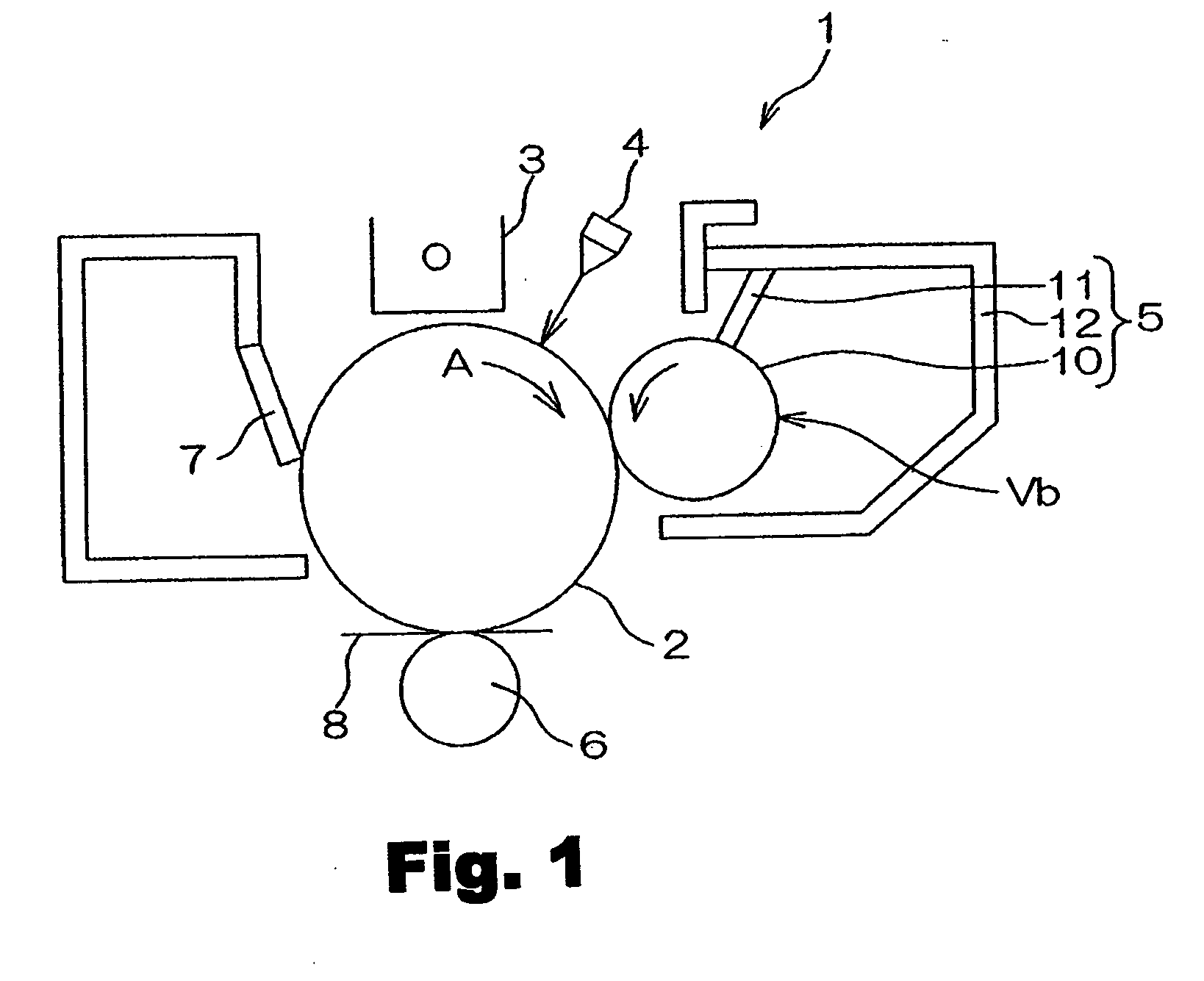
[0025]FIG. 1 is a schematic vertical cross-sectional view showing an outline of the structure of a main part of the imaging apparatus according to a preferred embodiment of the present invention. In reference to FIG. 1, an imaging apparatus 1 is, e.g., a photocopying machine, a printer, or a fax machine, and the apparatus uses an electrophotographic method to form an electrostatic latent image based on image data. The electrostatic latent image is developed using a toner, a toner image is formed, and the toner image is transferred to paper.

[0026] The imaging apparatus 1 has a photoreceptor drum ...


PUM


Abstract

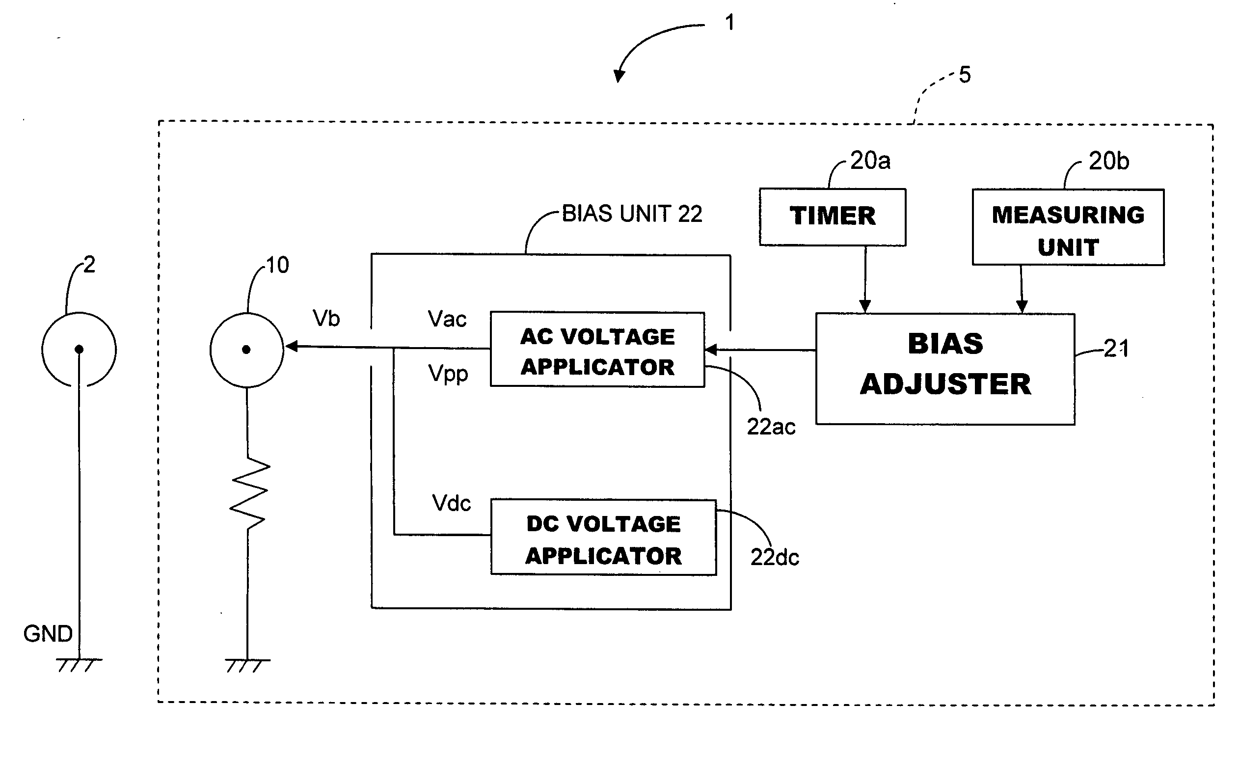
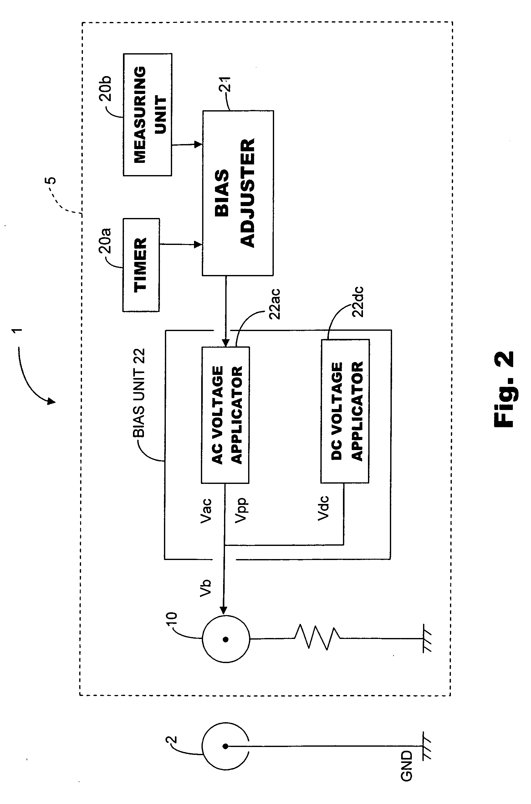
The developing apparatus of the present invention is a developing apparatus that develops an electrostatic latent image using a two-component developer containing a toner and a carrier; wherein the developing apparatus has a developing roller that rotates with a developer adhering to the peripheral surface thereof in order to transfer the developer to an electrostatic latent image; a bias unit having a DC voltage applicator that applies a prescribed DC voltage to the developing roller and an AC voltage applicator that applies an AC voltage to the developing roller; a timer that measures the developing apparatus drive time; a measuring unit that measures the amount of developing performed by the developing apparatus; and a bias adjustor whereby the amplitude component of the AC voltage applied by the AC voltage applicator is lowered based on an increase in output of the timer and / or the measuring unit.

Description

CROSS-REFERENCE TO RELATED APPLICATIONS [0001] This application claims priority to Japanese Patent Application No. 2005-359225 filed on Dec. 13, 2005. The entire disclosure of Japanese Patent Application No. 2005-359225 is hereby incorporated herein by reference. BACKGROUND OF THE INVENTION [0002] 1. Field of the Invention [0003] The present invention generally relates to a developing apparatus and an imaging apparatus having the developing apparatus. More specifically, the present invention relates to an apparatus that develops an electrostatic latent image using a two-component developer containing a toner and a carrier. [0004] 2. Background Information [0005] In photocopying machines, printers, fax machines, and other imaging devices, for example, an electrostatic latent image is formed by an electrophotographic method in which a uniformly charged photoreceptor drum is selectively exposed. Developing apparatuses in which toner is used to develop the electrostatic latent image are...

Claims


Application Information

Patent Timeline
IPC IPC(8): G03G15/06
CPCG03G15/065G03G2215/0609
Inventor WATANABE, YOICHIRO
Owner KYOCERA DOCUMENT SOLUTIONS INC
Learn More