Rechargeable vacuum cleaner

Inactive Publication Date: 2007-06-21
ZWEITA INT
View PDF5 Cites 79 Cited by
  • Summary
  • Abstract
  • Description
  • Claims
  • Application Information

AI Technical Summary

Benefits of technology

[0013] The present invention has the advantages as follows. The installation of more than one set of rechargeable batteries using the technique of voltage dividing can lengthen the operating time of the rechargeable vacuum cleaner. Further, the sets of rechargeable batteries will be

Problems solved by technology

Therefore, a rechargeable vacuum cleaner with only one set of rechargeable batteries has a short operating time, and continuously charging the set of rechargeable batteries is necessary for continuously using the rechargeable vacuum cleaner.
However, this design cannot solve the problem of short lifespan of a set of r

Method used


Image

  • Rechargeable vacuum cleaner
  • Rechargeable vacuum cleaner
  • Rechargeable vacuum cleaner

Examples


Example

[0025] The various objects and advantages of the present invention will be more readily understood from the following detailed description when read in conjunction with the appended drawings.

[0026] The objective of the present invention is using the technique of voltage dividing to rechargeable vacuum cleaners equipped with more than one sets of rechargeable batteries, whereby the input voltage of the motor is kept constant when: (1) one of the sets of rechargeable batteries is used alone; (2) two sets of rechargeable batteries are used together; and (3) there is an imbalance in electricity capacity over the sets of rechargeable batteries.

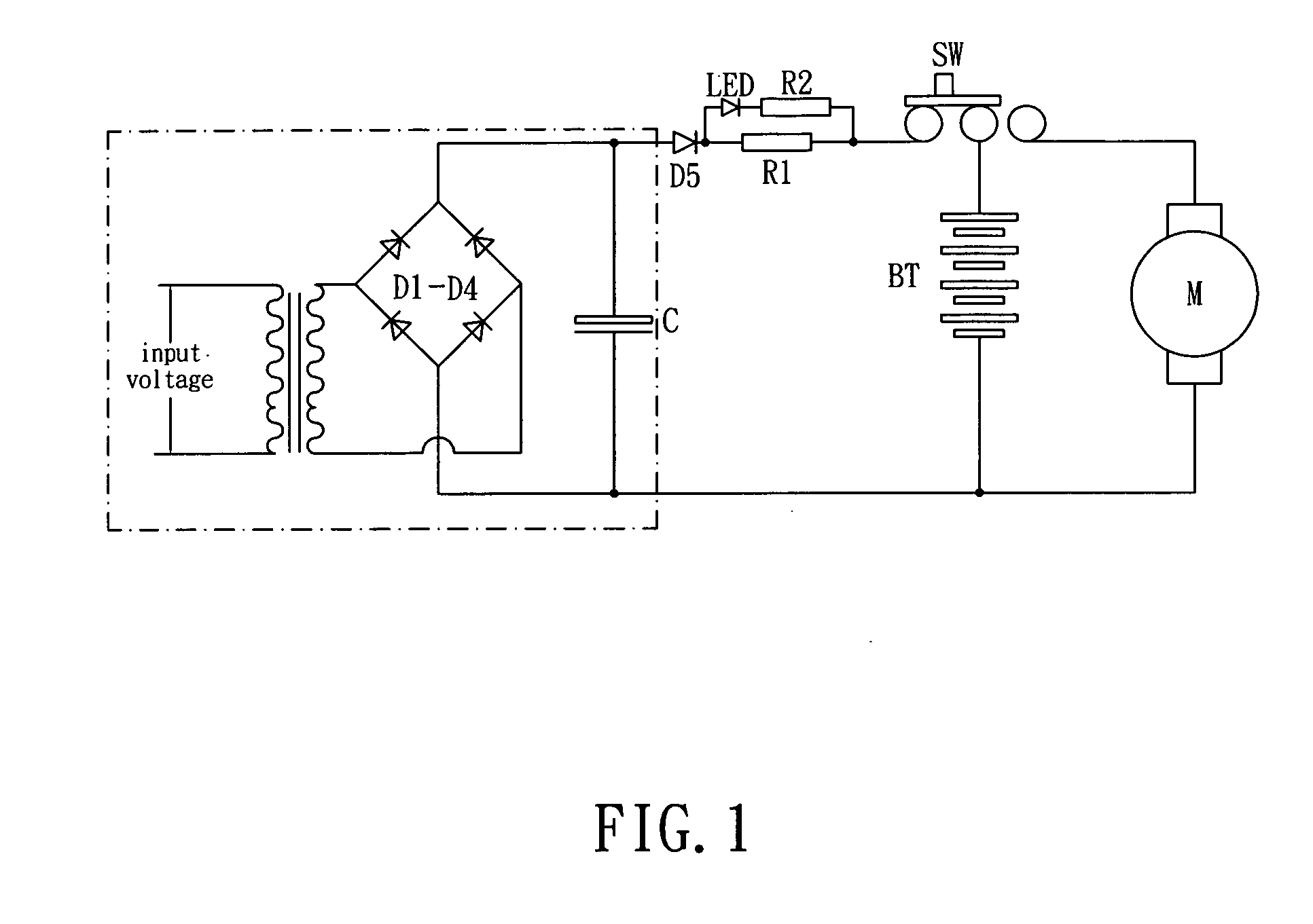
[0027] Referring to FIG. 4, the positive-polarity terminals of two sets of rechargeable batteries BT1, BT2 are connected to a terminal of a motor through a power-supply control unit, selected from a silicon assembly and a diode. The negative-polarity terminals of the sets of rechargeable batteries BT1, BT2 are connected to the other terminal of t...


PUM


Abstract

A rechargeable vacuum cleaner comprises a main body, at least two sets of rechargeable batteries for driving a motor in the main body and a power-supply control unit. The power-supply control unit is coupled with the sets of rechargeable batteries and the motor for affecting a set of rechargeable batteries of higher voltage to supply power to the motor and for preventing the set of rechargeable batteries charging another set of rechargeable batteries of lower voltage. The power-supply control unit includes a silicon assembly (being a bridge rectifier) or a diode. The rechargeable vacuum cleaner can be of two piece type (with a detachable unit) or a two piece type. Therefore, the rechargeable vacuum cleaner can lengthen the operating time and prevent damaging the batteries.

Description

BACKGROUND OF THE INVENTION [0001] (a) Field of the Invention [0002] The present invention relates to rechargeable vacuum cleaners, more particularly to a rechargeable vacuum cleaner utilizing the technique of voltage dividing to lengthen the operating time and the lifespan of its batteries. [0003] (b) Description of the Prior Art [0004] The majority of the rechargeable vacuum cleaner of prior art use a set of rechargeable batteries connected in parallel to supply a motor, such as four 12V 1300 mA batteries with an output voltage of 4.8V. The motor is then used to provide an effect of vacuum cleaning. As shown in FIG. 1, the electric circuit of a rechargeable vacuum cleaner of the prior art comprises a charging circuit and a power supplying circuit attached with a set of rechargeable batteries for powering a motor. The power supplying circuit further includes a switch for controlling charging and power-supplying of the set of rechargeable batteries. The operating time of the vacuum ...

Claims


Application Information

Patent Timeline
IPC IPC(8): A47L9/00A47L5/00
CPCA47L5/225A47L5/24A47L5/28A47L9/2884
Inventor HSU, CHIH KAO
Owner ZWEITA INT
Why Eureka
Try Eureka