Gearing apparatus
- Summary
- Abstract
- Description
- Claims
- Application Information
AI Technical Summary
Benefits of technology
Problems solved by technology
Method used
Image
Examples
Example
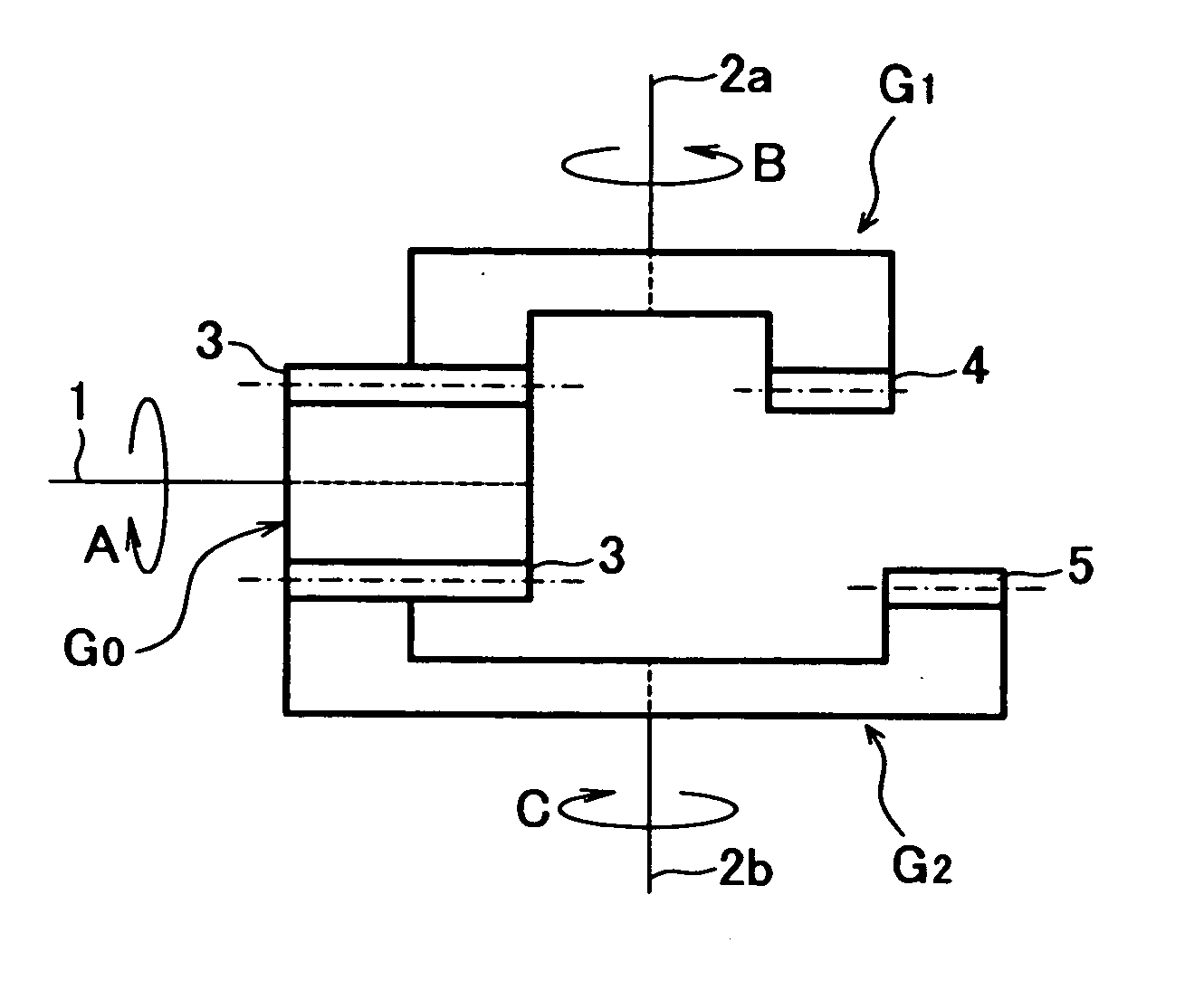
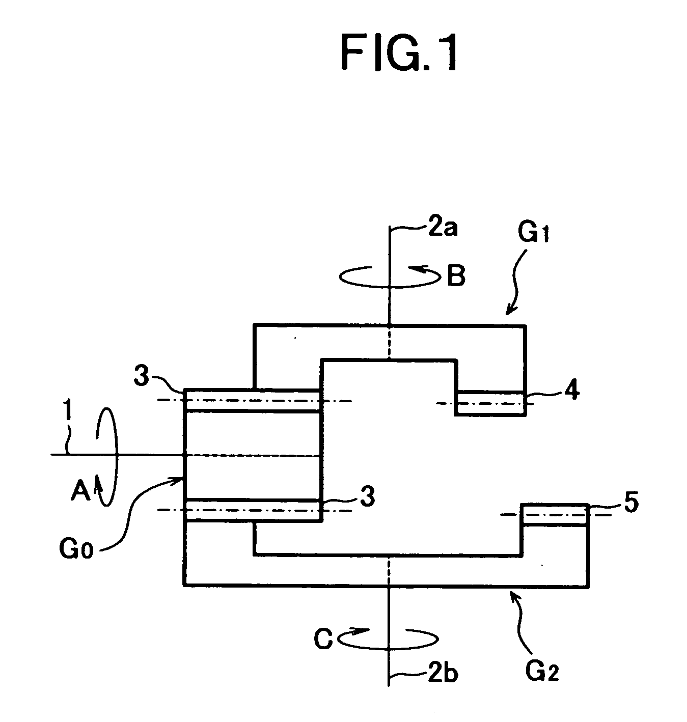
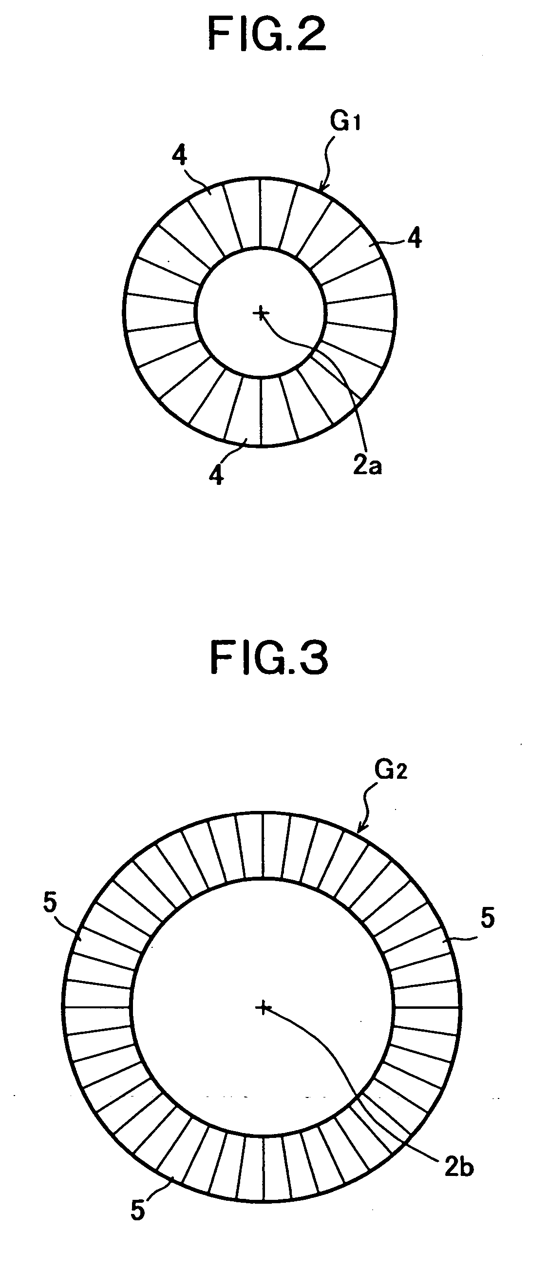
[0037]FIG. 5 is a perspective view showing a gearing apparatus according to a second embodiment of the present invention. In this embodiment, the driving gear G0 comprised of a helical gear, and the first and second driven gears G1 and G2, each comprised of a disc shape face gear to be engaged with the helical gear of the driving gear G0. As will be understood from FIG. 5 showing a state of engagement of the driving gear G0 comprised of the helical gear with the second driven gear G2, a plurality of teeth (helical teeth) designated by reference numeral 3′ is formed in the outer circumferential surface of the driving gear G0, and a plurality of helically extending teeth designated by reference numeral 5′ is formed in the outer peripheral surface of the second driven gear G2. The configuration of the second embodiment other than the above is similar to that of the first embodiment shown in FIG. 1. Here, for the sake of simplicity of the drawing figure, the first driven gear G1 is omit...
Example
[0038]FIG. 6 is a schematic diagram showing a gearing apparatus according to a third embodiment of the present invention. In this embodiment, the driving gear G0 is provided in the circumference thereof with gear teeth arranged in two separate regions axially divided within the tooth width thereof, so that each of the separate regions has the different number of teeth. Namely, the tooth width of the driving gear G0 is formed to be divided at, for example, a center portion thereof into regions 3a and 3b in which the number of teeth provided in the tooth width region 3a is Na and the number of teeth provided in the tooth width region 3b is Nb. Then, the tooth width region 3a of the driving gear G0 is engaged with the first driven gear G1, while the tooth width region 3b being engaged with the second driven gear G2.
[0039] In this state, the number of teeth in the teeth 3 of the driving gear G0 is in two types of Na and Nb, and if the number of teeth in the teeth 4 of the first driven ...
Example
[0042]FIG. 7 is a schematic diagram showing a gearing apparatus according to a fourth embodiment of the present invention. In this embodiment, the driving gear G0 is formed to have two separate regions within the tooth width thereof, so that diametrical dimensions of the respective separate regions are designed so as to be different from each other thereby forming a large diameter portion G01 and a small diameter portion G02, and also, the large diameter portion G01, and the small diameter portion G02 have a plurality of teeth on the circumferences thereof, respectively, which are different in the number from each other. Namely, the entire tooth width of the driving gear G0 is separated at, for example, the center portion thereof into two regions 3a and 3b, so that the tooth width region 3a is made to be a large diameter portion G01, the tooth width region 3b is made to be a small diameter portion G02, the number of teeth in the large diameter portion G01 is set to be Nc and the num...
PUM
 Abstract
Description
Claims
Application Information
 - R&D
- Intellectual Property
- Life Sciences
- Materials
- Tech Scout
- Unparalleled Data Quality
- Higher Quality Content
- 60% Fewer Hallucinations
Browse by: Latest US Patents, China's latest patents, Technical Efficacy Thesaurus, Application Domain, Technology Topic, Popular Technical Reports.
© 2025 PatSnap. All rights reserved.Legal|Privacy policy|Modern Slavery Act Transparency Statement|Sitemap|About US| Contact US: help@patsnap.com


