
Resonant dc/dc power converting circuit and method for controlling the same

Active Publication Date: 2016-06-30
DELTA ELECTRONICS INC
View PDF8 Cites 16 Cited by
  • Summary
  • Abstract
  • Description
  • Claims
  • Application Information

AI Technical Summary

Benefits of technology

The present invention provides a solution to the problem of resonant converters being unable to achieve current balance by adjusting signal frequencies. The invention is a resonant DC / DC power converting circuit and a method for controlling it that improves this issue.

Problems solved by technology

As a result, a defect is generated.
In practical applications, parameters of the interleaved parallel converter circuit unavoidably have deviations.
Hence, how to use an active current-balance control to balance the output powers of the converters has become a major issue confronted by the industry.
As a result, the switching frequency of the converters needs to be adjusted simultaneously, which causes that the resonant converter cannot achieve current balance through adjusting the duty ratio like the PWM converter and needs to adjust signal frequencies to achieve the objective of current balance.

Method used


Image

  • Resonant dc/dc power converting circuit and method for controlling the same
  • Resonant dc/dc power converting circuit and method for controlling the same
  • Resonant dc/dc power converting circuit and method for controlling the same

Examples


Embodiment Construction

[0031]The detailed description provided below in connection with the appended drawings is intended as a description of the present examples and is not intended to represent the only forms in which the present example may be constructed or utilized. The description sets forth the functions of the example and the sequence of steps for constructing and operating the example. However, the same or equivalent functions and sequences may be accomplished by different examples.

[0032]Unless otherwise defined herein, scientific and technical terminologies employed in the present disclosure shall have the meanings that are commonly understood and used by one of ordinary skill in the art. Unless otherwise required by context, it will be understood that singular terms shall include plural forms of the same and plural terms shall include the singular.

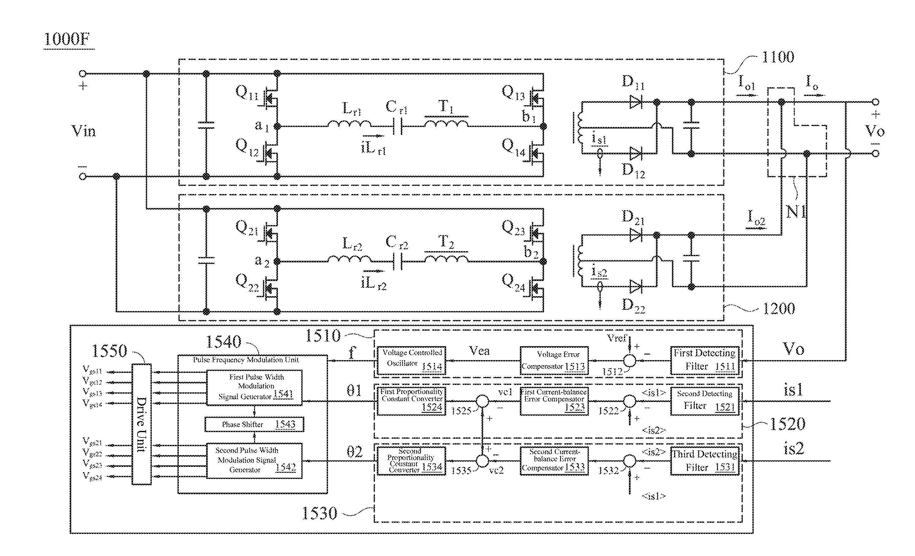
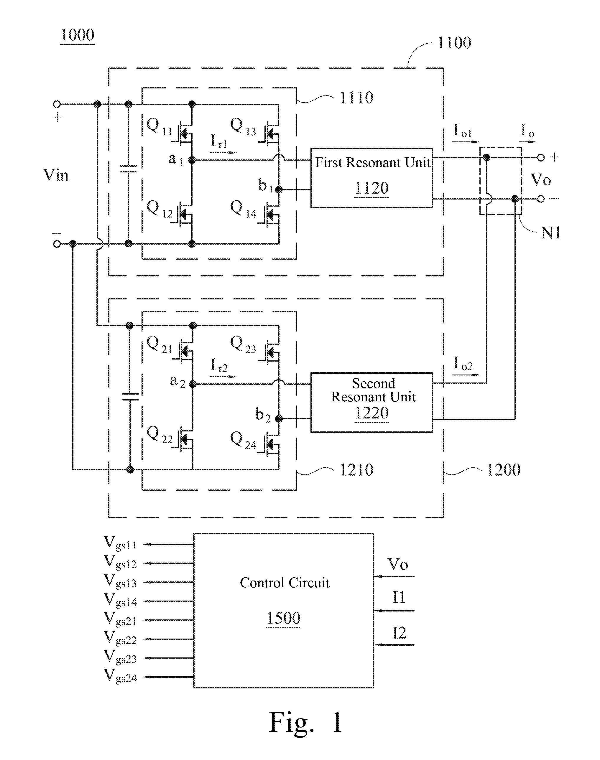
[0033]FIG. 1 depicts a schematic diagram of a resonant DC / DC power converting circuit 1000 according to one embodiment of this invention. As shown in...


PUM


Abstract

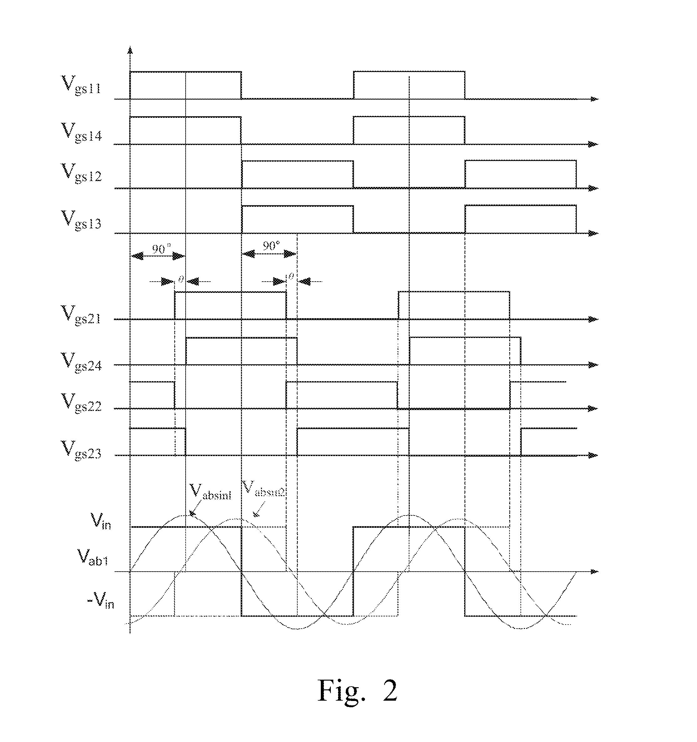
A method for controlling a resonant DC / DC power converting circuit is provided. The resonant DC / DC power converting circuit having a converter output and a converter input comprises at least two converters having similar structures and outputs connected in parallel as said converter output, and a controller. Each converter comprises a full-bridge inverter unit and a resonant unit. The full-bridge inverter unit is configured with at least four switches. The resonant unit is coupled with said full-bridge inverter unit. The controller outputs two groups of driving control signals to drive four switches in said two converters respectively. The method comprises: making said two converters operate at the same frequency and interleave with preset phase shift; and making two of driving control signals in one group interleave with preset angle to reduce output current of said converter corresponding controlled thereby, when output currents of said two converters are not approximately equal.

Description

RELATED APPLICATIONS[0001]This application claims priority to China Application Serial Number 201410825911.8, filed Dec. 25, 2014, which is herein incorporated by reference.BACKGROUND[0002]1. Field of Invention[0003]The present invention relates to a power converting circuit and a control method thereof. More particularly, the present invention relates to a resonant DC / DC power converting circuit and a method for controlling the same.[0004]2. Description of Related Art[0005]With the progress of science and technology, energy conversion and employment have become increasingly important. Among the various energy conversion technologies, since the resonant converters can achieve zero voltage switching (ZVS) and zero current switching (ZCS), devices are allowed to operate at a low turn-off current and high frequency. Therefore, resonant converters have been widely applied to high efficiency and high power density power supplies.[0006]However, when a single phase resonant converter is ap...

Claims


Application Information

Patent Timeline
IPC IPC(8): H02M3/335
CPCH02M3/33507H02M3/285H02M1/0058Y02B70/10
Inventor YAN, CHAOYE, YI-QINGLIAN, ZHI-ZHEN
Owner DELTA ELECTRONICS INC
Learn More