Mooring anchor system for wave energy converters (WECS)

Active Publication Date: 2014-05-29
OCEAN POWER TECHNOLOGIES
View PDF1 Cites 17 Cited by
  • Summary
  • Abstract
  • Description
  • Claims
  • Application Information

AI Technical Summary

Benefits of technology

[0009]For example, a first anchor defining a first anchor row and a first WEC defining a first WEC row form the apex of a triangular formation. A second row of anchors comprising 2 anchors is formed below the first WEC row and a second WEC row comprising 2 WECs is formed below the second anchor row. Then a third row of anchors comprising 3 anchors is formed belo

Problems solved by technology

However, a problem with this practice is that when many WECs are used for increasing the amount of generated power, the

Method used


Image

  • Mooring anchor system for wave energy converters (WECS)
  • Mooring anchor system for wave energy converters (WECS)
  • Mooring anchor system for wave energy converters (WECS)

Examples


Example

DETAILED DESCRIPTION OF THE DRAWINGS

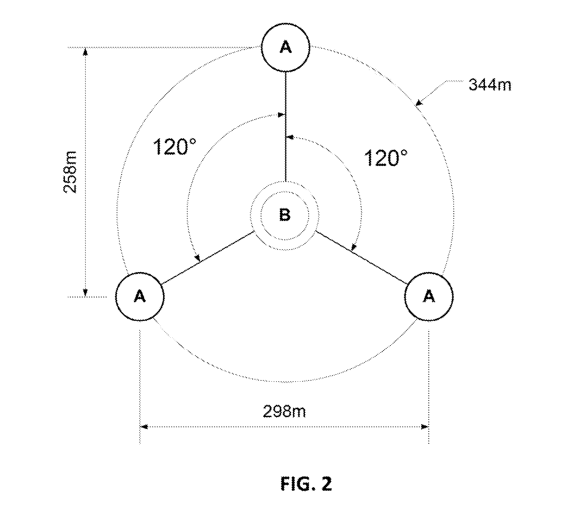
[0018]This invention relates to a mooring (anchoring) system for WECs to reduce the number of mooring anchors needed to maintain arrays of wave energy converters (WECs) disposed in a body of water in place and to thereby reduce the cost of mooring an array of WECs.

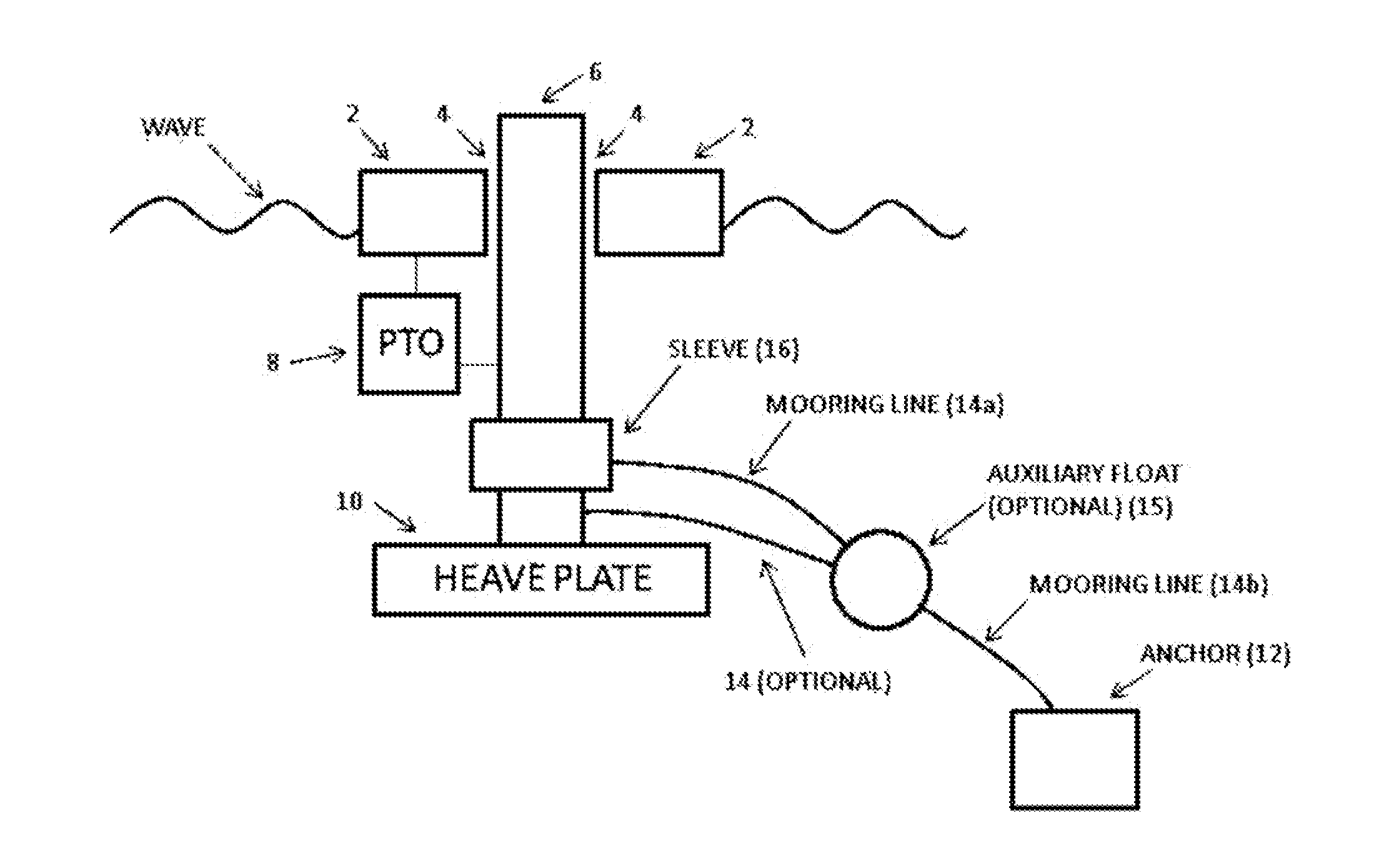
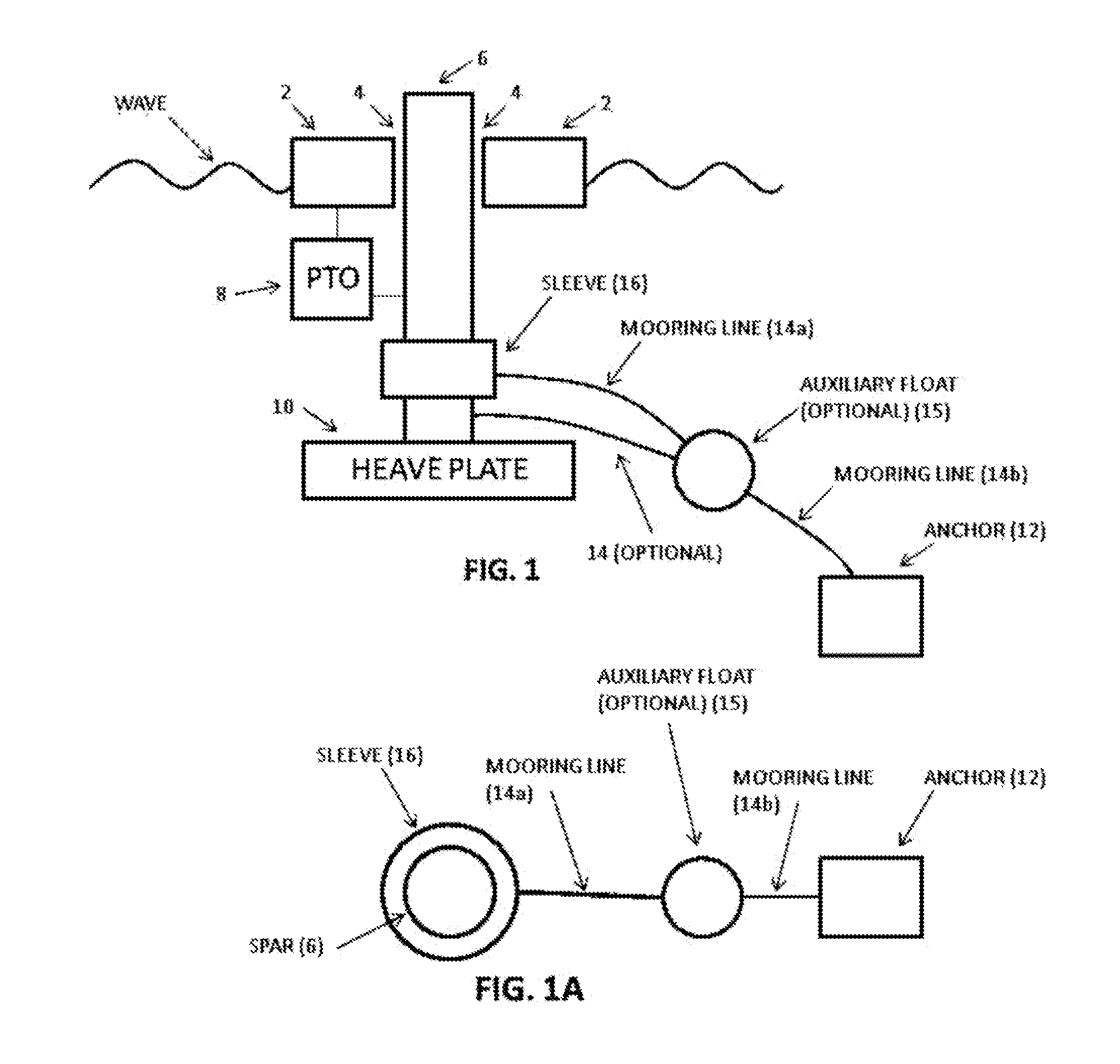
[0019]An example of a WEC suitable for use with the present invention is shown, schematically, in FIG. 1. The WEC includes a generally flat (toroidal) float 2 having a central opening 4 there through and an elongated float 6, referred to as a “spar”, slidably extending through the flat float central opening 4. The spar 6 and float 2 bob up-and-down in response to passing surface waves but in different phase relationships with the waves, hence there is relative motion between the spar and float. FIG. 1 shows that a heave plate 10 can be connected to spar 6 to increase its effective mass. The relative movements between the spar and float are used for generating useful energy by driving a p...


PUM


Abstract

A mooring system for a plurality of wave energy converters (WECs) includes a multiplicity of anchors coupled to form an array of contiguous hexagonal shaped cells. Each cell has 3 WECs and 3 anchors located at the vertices of the hexagon, with a WEC alternating with an anchor going around the perimeter of the cell. Except for the cells at the edges of the array, each WEC is connected to two anchors of its cell and an anchor of an adjacent contiguous cell. Each WEC is connected to three different anchors via 3 mooring lines spaced 120 degrees apart about the WEC. The ratio of the number of anchors per WEC is decreased by connecting each anchor to more than one WEC. The cells can be arranged to form many different patterns. In one embodiment a plurality of WECs and anchors are deployed in a generally triangular formation extending from an apex of the triangular formation to a base.

Description

BACKGROUND OF THE INVENTION[0001]This invention claims priority based on provisional application Ser. No. 61 / 629,809 filed Nov. 28, 2011, titled MOORING ANCHOR SYSTEM FOR MULTIPLE WAVE ENERGY CONVERTERS (WECS), whose teachings are incorporated herein by reference.[0002]This invention relates to wave energy converters (WECs) for converting energy in the waves on the surface of bodies of water to useful energy and, in particular, to the mooring or anchoring of multiple groups or arrays of WECs of the floating buoy type.[0003]One known type of WEC (also referred to herein as a “buoy”), with which the present invention is primarily concerned, comprises a WEC having components (e.g., a float and a spar) which move relative to each other, or are driven into movement, in response to passing surface waves. The relative movement of the components is used for driving an energy transducer (also referred to herein as a power take off device (PTO) for generating useful energy. For retaining WECs...

Claims


Application Information

Patent Timeline
IPC IPC(8): F03B13/18
CPCF03B13/18F05B2240/40F05B2240/97Y02E10/30
Inventor HART, PHILIP R.
Owner OCEAN POWER TECHNOLOGIES
Why Eureka
Try Eureka