Gears and gearing apparatus
- Summary
- Abstract
- Description
- Claims
- Application Information
AI Technical Summary
Benefits of technology
Problems solved by technology
Method used
Image

Examples
second embodiment
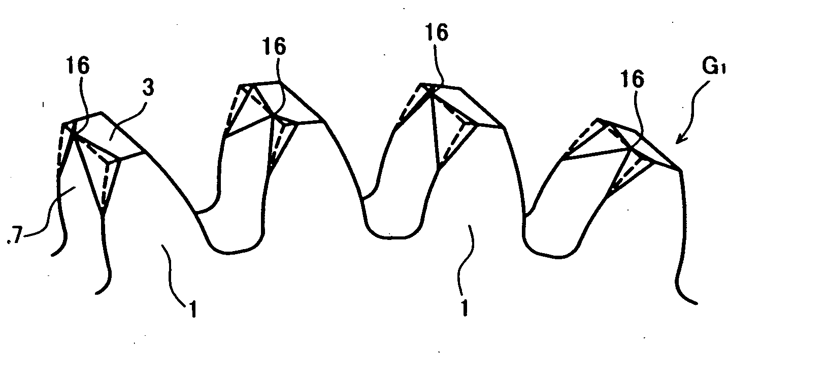
[0064]FIG. 6 is a main part perspective view showing the shape of the tooth 1 of the gear G1. In this embodiment, the predetermined region A in the tooth flank is chamfered so that the configuration thereof is made to be inclined planes which extend from the one place in the tooth width direction on the crossing 8 of the one tooth flank 7 and the tooth tip surface 3 to both of the end faces of the tooth 1. Namely, chamfered portions 9a and 9b are formed, by cutting away from the one tooth flank 7 predetermined places in the tooth width direction on the crossing 8 of the one tooth flank 7 and the tooth tip surface 3 in triangular inclined planes, in this case, from a center portion 16 toward the involute curve portions on the end portion 5 and 6 sides on both sides.
[0065] According to such a shape, the configuration of the predetermined region A in at least the one tooth flank 7 of each tooth 1 can be formed such that the mating with the teeth (2) of the mating gear (G2) starts from ...
third embodiment
[0069]FIG. 9 is a main part perspective view showing the shape of the tooth 1 of the gear G1. In this embodiment, chipped portions 17a and 17b are formed so that the configuration of the predetermined region A in the tooth flank is made to be inclined planes which extend from the one place on the one tooth flank 7 to both of the end face sides toward the crossing 8 of the tooth flank 7 and the tooth tip surface 3. Namely, the chipped portions 17a and 17b are formed, by chipping off from the tooth flank 7 the triangular inclined planes which extend from a site 18 of the one place on the one tooth flank 7 to both of the end face sides toward the crossing 8 of the tooth flank 7 and the tooth tip surface 3.
[0070] According to such a shape, the configuration of the predetermined region A in at least the one tooth flank 7 of each tooth 1 can be formed such that the mating with the teeth (2) of the mating gear (G2) is started from the corner portion on the one end portion 5 side or the oth...
fourth embodiment
[0075]FIG. 13 is a main part perspective view showing the shape of the tooth 1 of the gear G1. In this embodiment, for the predetermined region A in the tooth flank, a curved surface 19 which gradually decreases the tooth thickness is formed from the one end face of the tooth toward the other end face thereof in the tooth width direction of the one tooth flank 7. Namely, the curved surface 19 is formed in a convex curved surface, and smoothly connects with parallel curves 22 between an involute curve 20 on the one end portion 5 side in the tooth width direction of the one tooth flank 7 and a curve 21 which modifies the tooth thickness of the tooth tip surface 3 on the other end portion 6 side with a modification amount p. At this time, a planar vision shape of the curved surface 19 viewed from above the tooth tip surface 3 of the tooth 1 in FIG. 13 is shown in FIG. 14, in which a curvature radius r of the curved surface 19 in the tooth width direction is sequentially increased from ...
PUM
 Abstract
Description
Claims
Application Information
 - Generate Ideas
- Intellectual Property
- Life Sciences
- Materials
- Tech Scout
- Unparalleled Data Quality
- Higher Quality Content
- 60% Fewer Hallucinations
Browse by: Latest US Patents, China's latest patents, Technical Efficacy Thesaurus, Application Domain, Technology Topic, Popular Technical Reports.
© 2025 PatSnap. All rights reserved.Legal|Privacy policy|Modern Slavery Act Transparency Statement|Sitemap|About US| Contact US: help@patsnap.com