Spin cleaning apparatus and wafer cleaning method
- Summary
- Abstract
- Description
- Claims
- Application Information
AI Technical Summary
Benefits of technology
Problems solved by technology
Method used
Image
Examples
example 1
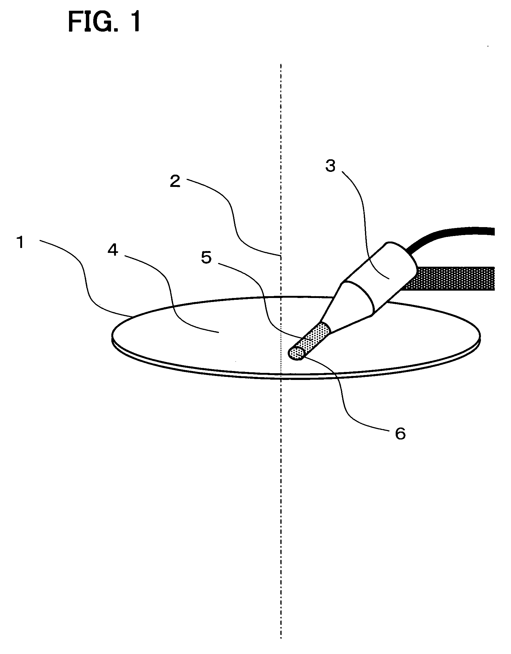
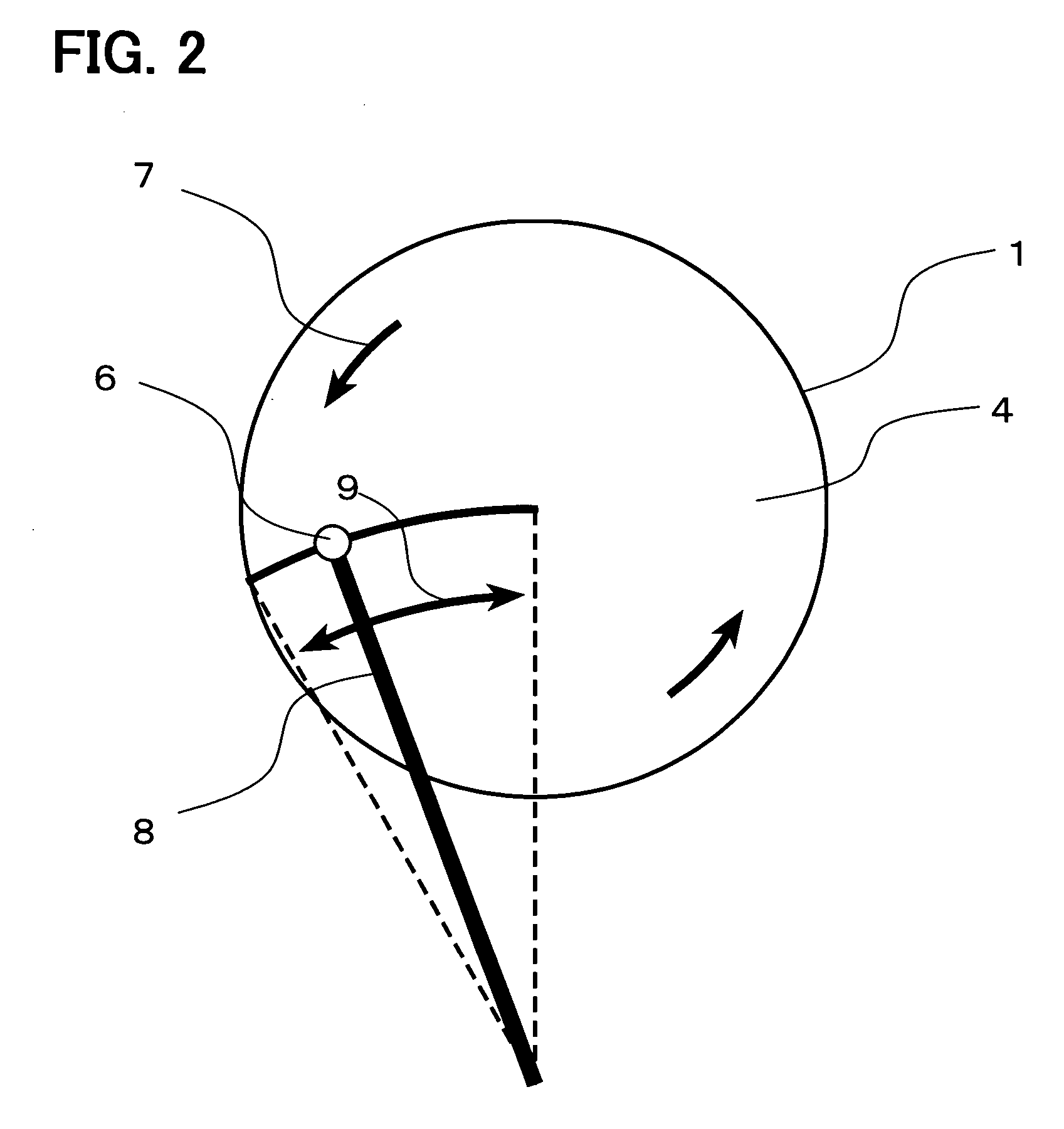
[0096] Then, cleaning similar to the above description was performed under the following settings, utilizing a function according to the present invention, i.e. a function capable of automatically setting the ultrasonic wave at ON / OFF, correspondingly to the position of the cleaning liquid collision spot. That is, the ultrasonic wave was set at OFF only at the positions where the movement direction of the cleaning liquid collision spot was reversed. More specifically, the cleaning was performed under the following conditions: the ultrasonic wave was made OFF for 0.3 sec in synchronization with the stationary period of the cleaning liquid collision spot, that is, only at the positions of r=0 and r=100 in the case in which the range of movement of the cleaning liquid collision spot was 0≦r≦100, and only at the positions of r=30 and r=100 in the case in which the range of movement of the cleaning liquid collision spot was 30≦r≦100. The results of pattern inspection are shown in FIG. 3 ...
example 2
[0097] Next, utilizing a function capable of automatically varying the rotation frequency of the wafer according to the present invention, correspondingly to the position of the cleaning liquid collision spot, the setting was made so that the sample wafer was rotated at a faster speed where the cleaning liquid collision spot was located at the position nearer to the center of the wafer. Also, utilizing a function capable of automatically varying the traveling speed of the nozzle correspondingly to the position of the cleaning liquid collision spot, the setting was made so that the cleaning liquid collision spot was reciprocated at a faster speed where the cleaning liquid collision spot was located at the position nearer to the center of the wafer. Specifically, the settings were made, respectively, so that the relationship between the nozzle position r (which coincides with the position of the cleaning liquid collision spot) and the rotation frequency ω of the wafer had the relation...
example 3
[0100] Next, cleaning was performed, simultaneously applying the settings of the ultrasonic wave at ON / OFF, the rotation speed of the wafer, and the traveling speed of the cleaning liquid collision spot, corresponding to the position of the cleaning liquid collision spot, each having been applied in examples 1 and 2.
[0101] The result of pattern inspection regarding the case of 0≦r≦100 is shown in Table 7. No breakage of pattern was produced any more.
[0102] Furthermore, experiments were performed in which fine particles were attached intentionally onto the surface of the wafer on which no patterns had been formed, and then cleaning was performed to remove the fine particles. As a result, it was confirmed that, as compared with the cleaning without the settings of this example, the cleaning under the settings of this example provided the same level of removal capability of the fine particles.
PUM
| Property | Measurement | Unit |
|---|---|---|
| Fraction | aaaaa | aaaaa |
| Length | aaaaa | aaaaa |
| Length | aaaaa | aaaaa |
Abstract
Description
Claims
Application Information
 - R&D
- Intellectual Property
- Life Sciences
- Materials
- Tech Scout
- Unparalleled Data Quality
- Higher Quality Content
- 60% Fewer Hallucinations
Browse by: Latest US Patents, China's latest patents, Technical Efficacy Thesaurus, Application Domain, Technology Topic, Popular Technical Reports.
© 2025 PatSnap. All rights reserved.Legal|Privacy policy|Modern Slavery Act Transparency Statement|Sitemap|About US| Contact US: help@patsnap.com


