Battery powered grease gun with strain gauge based pressure transducer

a technology of pressure transducer and grease gun, which is applied in the direction of mechanical equipment, machines/engines, transportation and packaging, etc., can solve the problems of grease leakage and damage to the seal components of the grease, possible explosion of the grease gun, wear and tear of the compression mechanism of the grease gun

Inactive Publication Date: 2007-06-21
WEEMS IND INC
View PDF15 Cites 22 Cited by
  • Summary
  • Abstract
  • Description
  • Claims
  • Application Information

AI Technical Summary

Benefits of technology

The technical effect that this technology helps detect when there's too much or too little lubricant inside your oil-filled cartridge during use by monitoring its pressures over time can help prevent damage from excessive usage caused by insufficient lubrication.

Problems solved by technology

The technical problem addressed in this patent text is the potential for overpressure and damage to the grease gun when using a battery powered grease gun and encountering a clogged grease zerk. There is a need for a solution to alert the user to the pressure of the grease in the gun or when the grease is under excess pressure.

Method used


Image

  • Battery powered grease gun with strain gauge based pressure transducer
  • Battery powered grease gun with strain gauge based pressure transducer
  • Battery powered grease gun with strain gauge based pressure transducer

Examples


Embodiment Construction

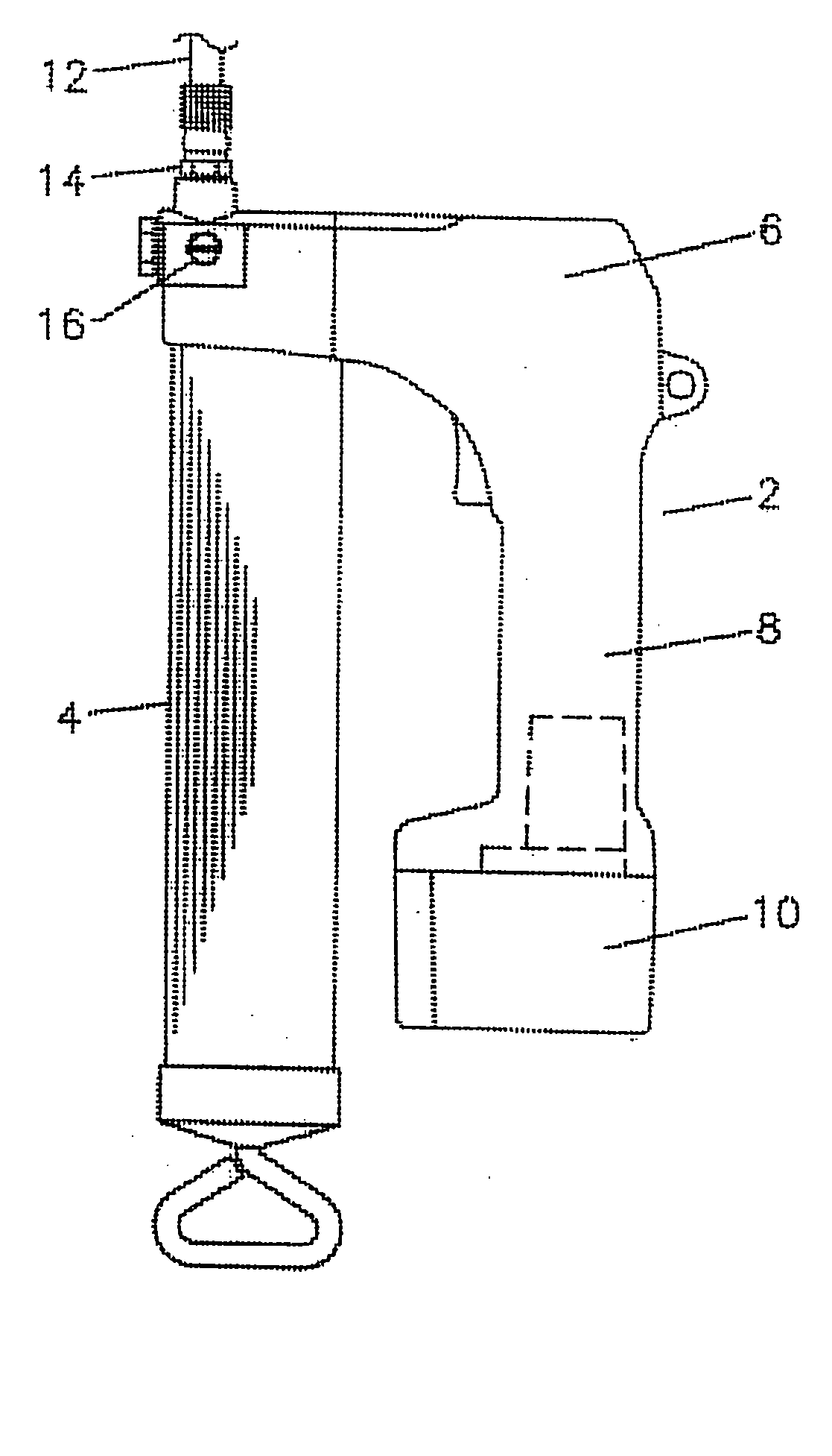
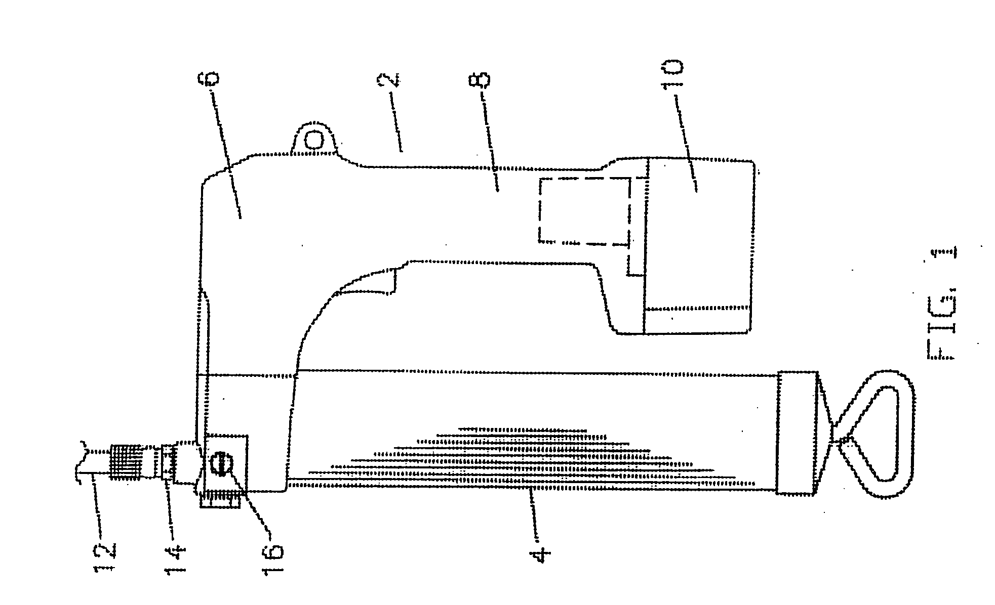
[0025] Referring to FIG. 1, an exemplary portable grease gun 2 is illustrated which includes a barrel 4 containing a supply of grease and a grease gun head 6 joined to a handle 8. A battery 10 is coupled electronically and mechanically to handle 8. The grease gun head 6 is coupled to a grease conduit 12 such as a flexible hose by fittings 14. An adjusting screw 16 is provided on the grease gun head 6 to permit a user to adjust the pressure of grease within the head at which grease will be bled off to the barrel 4. This adjusting screw may additionally be fitted with an external pointer (not shown) to allow the user to set a desired pressure when aligned with a calibrated dial on the head. The adjusting screw may alternatively be adjustable with the use of a tool such as an allen wrench or a screwdriver, or it may be provided with a knob which can be restricted manually. The grease barrel 4 may be removed and an adapter for attachment of a hose attached in the place of barrel 4. The ...


PUM


Abstract

A battery powered grease gun is disclosed. One embodiment has an overpressure relief valve for returning grease to the grease barrel mounted to the grease gun head when a plugged zerk prevents grease from exiting the output port. The grease gun head may be additionally provided with a sampling duct which is joined to an output port. The sampling duct couples the output port to another port in which a pressure gauge or a pressure transducer may be installed. In one embodiment, a strain gauge based pressure transducer may be attached to the grease gun to monitor the flow and pressure of grease in the grease gun. The pressure and/or flow of grease may be displayed on the pressure gauge or on a display coupled to the transducer.

Description


Claims


Application Information

Patent Timeline
Owner WEEMS IND INC
Why Eureka
Try Eureka