Cushion of air bag module

a technology of airbag module and cushion, which is applied in the direction of vehicle components, pedestrian/occupant safety arrangements, vehicle arrangements, etc., can solve the problems of mechanical energy loss, uneven deployment, energy loss, etc., and achieve the effect of reducing the loss of dynamic energy and smooth switching of the gas flow direction

Inactive Publication Date: 2007-06-21
HYUNDAI MOBIS CO LTD
View PDF14 Cites 25 Cited by
  • Summary
  • Abstract
  • Description
  • Claims
  • Application Information

AI Technical Summary

Benefits of technology

[0024]The present invention is directed to solve the prior art problems, and has for its object to provide a cushion of an air bag module which can smoothly switch the flow direction of gas and reduce the loss of dynamic energy when the direction of the gas is switched by forming an eddy current of the gas within the cushion.

Problems solved by technology

As seen from above, the cushion 14 of the air bag module 2 is problematic in that it is not possible to deploy the head chamber part 22 until the static pressure of the gas emitted into the thorax chamber part 20 reaches a predetermined value, and the static pressure is converted into a dynamic pressure in the direction of the head chamber part 22 after the dynamic pressure of the gas is converted into a static pressure in the thorax chamber part 20, thereby causing an energy loss.
Moreover, the loss of mechanical energy occurs in the procedure of the gas flowing into the head chamber part 22 from the inner pocket 24, and hence the head chamber part 22 does not deploy smoothly and the deployment time of the head chamber part 22 is delayed.
As above, if the head chamber part 22 is not deployed in a precise shape at a proper time, the driver and the passenger are not effectively protected by the air bag module 2 in the event of a vehicle collision, which deteriorates the reliability and merchantability of the air bag system for a vehicle.

Method used


Image

  • Cushion of air bag module
  • Cushion of air bag module
  • Cushion of air bag module

Examples


first embodiment

[0046]FIG. 3 is a cross sectional view showing a cushion of an air bag module in accordance with the present invention. FIG. 6 is a reference diagram for explaining the shape and forming position of a diffuser provided in FIGS. 3 to 5, which is a graph about the Mach number of an outlet With respect to the area ratio of inlet to outlet of the diffuser.

[0047]For reference, the same reference numerals are used for the components same as those used in the prior art.

[0048]As shown in FIG. 3, the cushion of an air bag module in accordance with the first embodiment of the present invention includes: a first chamber part 52 which deploys to one side of an occupant by a high pressure gas delivered from an inflator 10; a second chamber part 54 which is formed to communicate with the first chamber part 52 and deploys to the other side of the occupant by the high pressure gas in the first chamber part 52; an inner pocket 56 which is mounted so on an inner side of the first chamber part 52 so a...

second embodiment

[0079]FIG. 4 is a cross sectional view showing a cushion of an air bag module in accordance with the present invention.

[0080]For reference, like reference numerals are used to designate elements corresponding to those described in the first embodiment of the present invention, thus a detailed description thereof will be omitted.

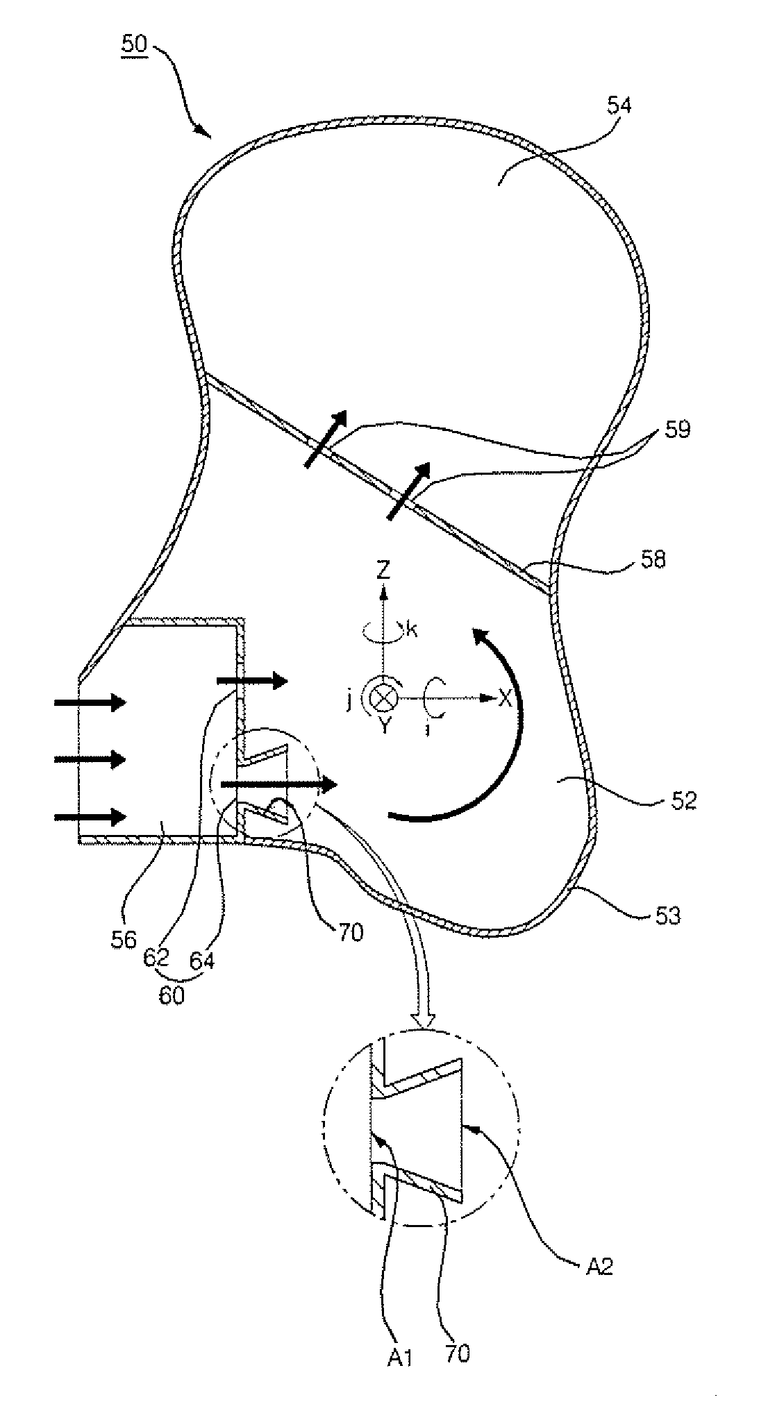
[0081]As shown in FIG. 4, in the cushion of an air bag module in accordance with the second embodiment of the present invention, gas is emitted at a flow velocity less than a supersonic velocity through first and second vent holes 62 and 64 of an inner pocket 56, and a diffuser 72 is formed in an inflatable nozzle structure in which its outlet cross sectional area A2 extends more than its inlet cross sectional area A1 does so that the flow velocity of the gas emitted from the second vent hole 64 is higher than the flow velocity of the gas emitted from the first vent hole 62. Other elements are constructed in the same manner as the first embodiment.

[0082]That ...

third embodiment

[0089]FIG. 5 is a cross sectional view showing a cushion of an air bag module in accordance with the present invention.

[0090]For reference, like reference numerals are used to designate elements corresponding to those described in the first embodiment of the present invention, thus a detailed description thereof will be omitted.

[0091]As shown in FIG. 5, in the cushion of an air bag module in accordance with the third embodiment of the present invention, an inner pocket 56 has a plurality of vent holes 60 spaced apart at through holes 59 of a barrier 58, and a diffuser 74 is provided at two or more of the vent holes 60 so that the flow velocity of the gas emitted from the vent holes 60 can increase as the gas becomes farther from the second chamber part 54. Other elements are constructed in the same manner as the first embodiment.

[0092]With respect to the plurality of diffusers 74, if the flow velocity of the gas emitted through the vent holes 0 is greater than a supersonic velocity,...


PUM


Abstract

The cushion of an air bag module includes a first chamber part which deploys to one side of an occupant by a high pressure gas of an inflator, a second chamber part which is formed to communicate with the first chamber part and deploys to the other side of the occupant by the high pressure gas in the first chamber part, an inner pocket which is mounted on an inner side of the first chamber part to introduce gas from the inflator and has a plurality of vent holes to emit the gas into the first chamber part, and a diffuser provided at the vent holes of the inner pocket so that the gas emitted from the inner pocket forms an eddy current at a side of the second chamber part.

Description

[0001]This Nonprovisional application claims priority under 35 U.S.C. §119(a) on Patent Application No. 10-2005-0123960 filed in Korea on Dec. 15, 2005, the entire contents of which are hereby incorporated by reference.BACKGROUND OF THE INVENTION[0002]1. Field of the Invention[0003]The present invention relates to an air bag module of an air bag system for a vehicle, and more particularly, to a cushion of an air bag module which can normally deploy the cushion and prevent a deployment time delay phenomenon by enhancing the flow of gas supplied into the cushion.[0004]2. Description of the Background Art[0005]Generally, an air bag system for a vehicle is a safety device for inflating an air bag module like a balloon upon the occurrence of a vehicle collision to thus alleviate an impact to a passenger and prevent the passenger from being thrown out of the vehicle by the cushioning action of an air bag module.[0006]Such an air bag system for a vehicle is classified into a number of type...

Claims


Application Information

Patent Timeline
Patent Type & Authority Applications(United States)
IPC IPC(8): B60R21/233B60R21/26
CPCB60R21/231B60R21/233B60R21/2346B60R2021/23324B60R21/207B60R21/23138B60N2/42B60R21/239
Inventor SONG, JUNE-YOUNG
Owner HYUNDAI MOBIS CO LTD
Why Eureka
Try Eureka