Methods and apparatus for a rugged mobile device housing

a mobile device and rugged technology, applied in the field of mobile device housings, can solve the problems of occupying a significant amount of space, requiring additional internal components or over-molded, and requiring wear-resistant plastics, so as to achieve high impact resistance, reduce deflection, and reduce the effect of bending

Inactive Publication Date: 2007-06-21
SYMBOL TECH INC
View PDF12 Cites 72 Cited by
  • Summary
  • Abstract
  • Description
  • Claims
  • Application Information

AI Technical Summary

Benefits of technology

[0006] In accordance with the present invention, a rugged mobile device housing for protecting a component (e.g., a liquid crystal display, a keyboard, a printed circuit board, or the like) includes one or more first structures comprising a first material provided in a region of the housing capable of withstanding deflection, wherein the first material is an elastomer, and one or more second structures bonded to the first structure, wherein the second structure ...

Problems solved by technology

Mobile devices such as cellular phones, personal data assistants (PDAs), and the like often incorporate components that are susceptible to shock damage incurred during an impact event.
Such frames, however, take up a signific...

Method used


Image

  • Methods and apparatus for a rugged mobile device housing
  • Methods and apparatus for a rugged mobile device housing
  • Methods and apparatus for a rugged mobile device housing

Examples


second embodiment

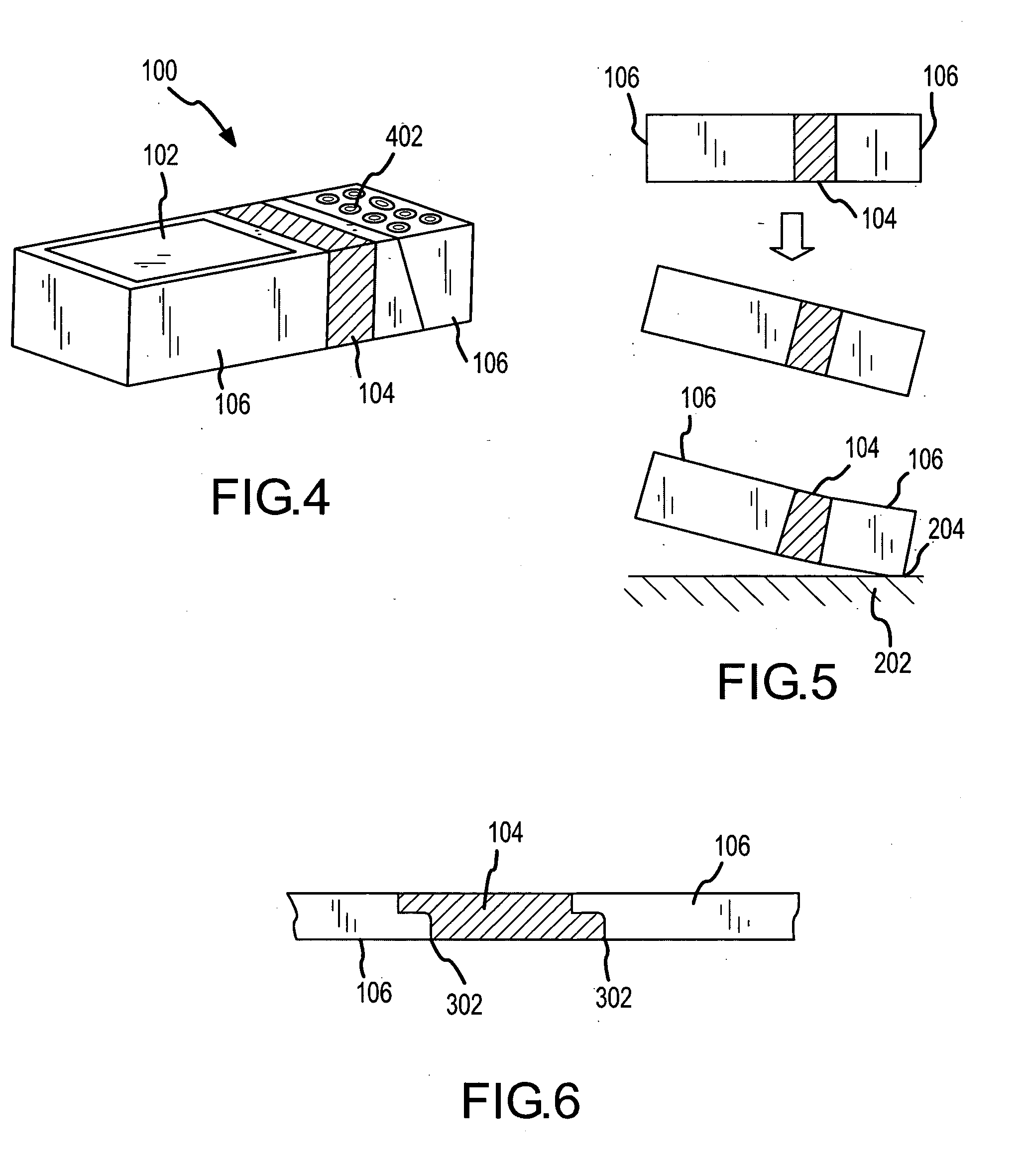
[0028]FIG. 4 presents a housing 100 for protecting a component 102. In this embodiment, a structure 104 comprising the first material is provided in a middle region of housing 100, while structures 106 are provided on one or more ends of the housing. In the illustrated embodiment, corresponding roughly to a conventional cellular phone configuration, a keyboard 402 is illustrated within one of the structures 106, and a component 102 (e.g., a display) is illustrated within the opposite structure 106. As shown in FIG. 5, a typical impact event would involve collision of the high-stiffness plastic structure 206 at a corner or edge 204, allowing central structure 104 to absorb the energy through elastic deformation. FIG. 6 depicts chemical bonding of stiff skeletal structures 106 (second material) to the sides of flexible center 104 (first material).

third embodiment

[0029]FIG. 7 presents a housing 100 that includes a projecting handle 702, a main body 704 (comprising one or more regions 106), and a hinge region defined by structure 104. Such an embodiment might correspond, for example, to a barcode scanner or other device that typically has a handle. Referring to FIG. 8, during a typical impact event, projecting handle 702 will impact at a point 204, allowing structure 104 to elastically deform, while structures 106 protect the attached components. As shown in FIG. 9, structures 106 form a stiff skeleton bonded to structure 104.

[0030] In general, the design principles set forth above may be used to develop ruggedized housings for any suitable application, while obviating the need for additional stiff internal structures. The first step, once the overall size and shape of the desired housing is determined, involves identifying which area or areas of the housing are capable of tolerating deflection (e.g., bending, twisting, etc.), and which canno...


PUM


Abstract

A rugged mobile device housing is provided for protecting a component (e.g., a liquid crystal display, a keyboard, a printed circuit board, or the like) and includes one or more first structures comprising a first material provided in a region of the housing capable of withstanding deflection, wherein the first material is an elastomer, and one or more second structures bonded to the first structure, wherein the second structure is a high-stiffness plastic. In one embodiment, the first material is a high-stiffness elastomer and the second material is a long glass fiber filled thermoplastic (“LGF” plastic). In one embodiment, the first structure is located at a corner of the housing and the second structure is located in the middle of the housing. In another embodiment, the first structure is located in the center of the housing and the second structures are located at the ends. In yet another embodiment, a projecting handle and hinge are provided, where the first structure is located at the handle and the second structure is located at the hinge.

Description

TECHNICAL FIELD [0001] The present invention relates generally to mobile device housings and, more particularly, to a rugged mobile device housing elastically tailored to the application and incorporating multiple materials. BACKGROUND [0002] Mobile devices such as cellular phones, personal data assistants (PDAs), and the like often incorporate components that are susceptible to shock damage incurred during an impact event. Such components include, for example, liquid crystal displays (LCDs), keyboards, printed circuit boards (PCBs), and other structures prone to breaking under moderate stress. [0003] Conventional housings aimed at addressing this problem in mobile devices often incorporate a stiff frame (e.g., a die-cast magnesium frame), which provides internal structure and thereby prevents large deflections. Such frames, however, take up a significant amount of space and add yet another costly component to the system. [0004] In order to accommodate sudden shock, conventional hou...

Claims


Application Information

Patent Timeline
IPC IPC(8): A47B81/06
CPCH05K5/0217
Inventor AUSTIN, TIMOTHYBHARGAVA, VIKRAMWULFF, THOMAS
Owner SYMBOL TECH INC
Why Eureka
Try Eureka