Method and apparatus for determining chrominance space

a chrominance space and method technology, applied in the direction of digitally marking record carriers, color signal processing circuits, instruments, etc., can solve the problems of increasing the power consumption of the chip, consuming much power of the chip, etc., to increase the multiplier circuit scale, increase the multiplier processing amount, and increase the chip power consumption

Inactive Publication Date: 2007-06-21
MONTEREY RES LLC +1
View PDF5 Cites 0 Cited by
  • Summary
  • Abstract
  • Description
  • Claims
  • Application Information

AI Technical Summary

Benefits of technology

[0017] In the determination method of FIG. 4, the outer products of the coordinates x, y of the input point P and the vectors (x1, y1 to x5, y5) of the five boundary lines L1 to L5 defining the regions A to E must be computed. Further, the multipliers 5a to 5k must perform multiplications for a number of times that is two times greater than the quantity of the boundary lines. As the number of regions increases, the multiplication processing amount drastically increases and enlarges the circuit scale of the multiplier. This increases the power consumption of the chip to which the multiplier is mounted.

Problems solved by technology

Further, the divider 1 and the calculation section 2 have a large circuit scale, and the chip to which the divider 1 and the calculation section 2 are mounted consume much power.
This increases the power consumption of the chip to which the multiplier is mounted.

Method used


Image

  • Method and apparatus for determining chrominance space
  • Method and apparatus for determining chrominance space
  • Method and apparatus for determining chrominance space

Examples


Embodiment Construction

[0030] A chrominance space region determination method according to a preferred embodiment of the present invention will now be discussed.

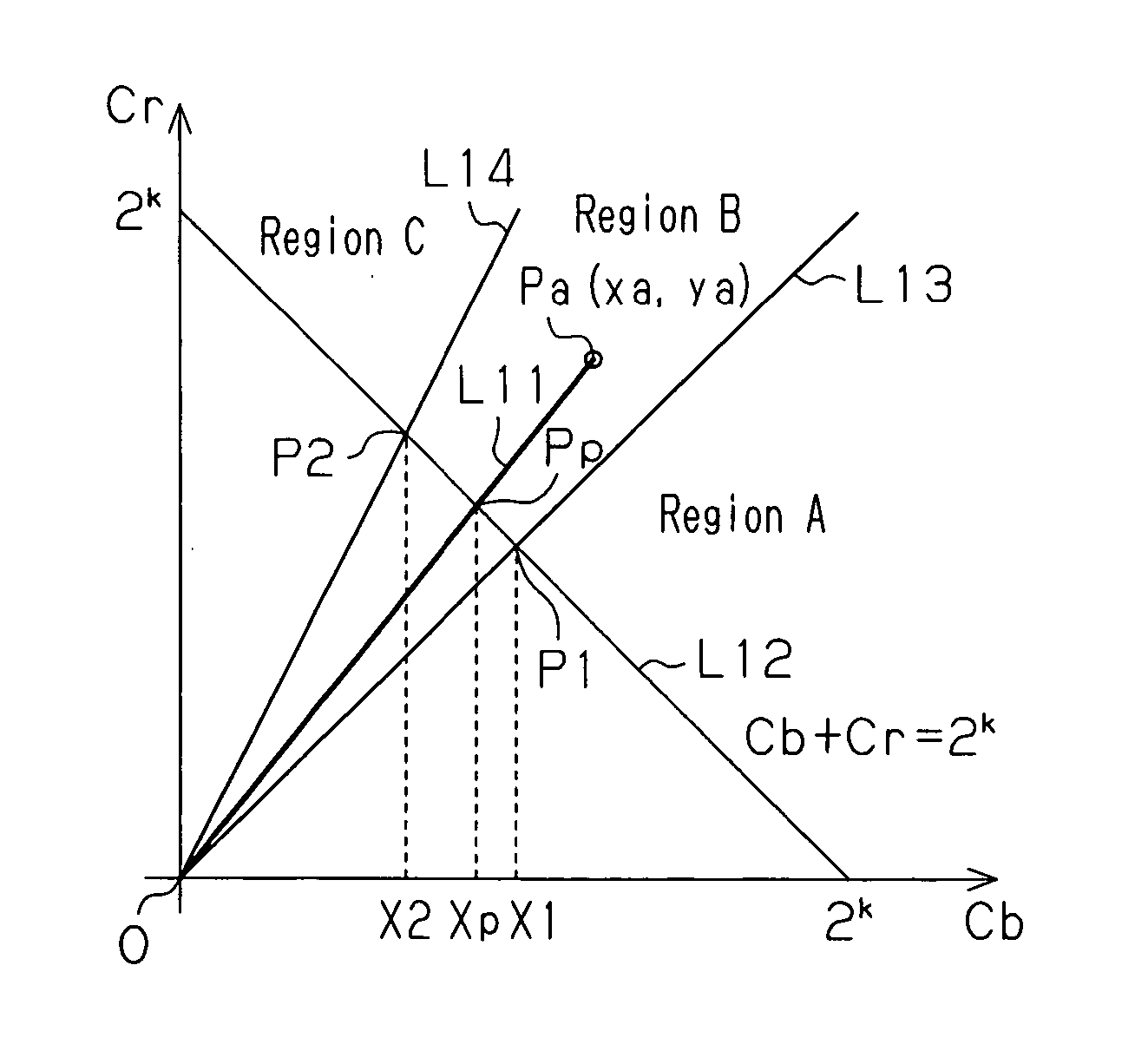
[0031] In FIG. 6, a line L11 (first line) connecting an input point P at coordinates x, y with origin O is represented by x·Cr=y·Cb. First, a Cb coordinates Xp of an intersection point Pp of the line L11 and a line L12 (second line) represented by Cb+Cr=2k (k=1, 2, 3, . . . ) is computed. The Cb coordinates Xp satisfies Xp=2k×x / (x+y).

[0032] Then, referring to FIG. 7, with regard to boundary lines L13 and L14 defining regions A to C in the chrominance region, Cb coordinates X1 and X2 of intersection points P1 and P2 of the boundary lines L13 and L14 and a line L12 are computed. The Cb coordinates X1 and X2 are boundary setting values.

[0033] Referring to FIG. 9, the coordinates X1 and X2, which are boundary setting values, and the coordinates Xp are compared to enable determination of which one of the regions to C the input point P (Pa in FIG. 9) ...


PUM

PropertyMeasurementUnit
coloraaaaaaaaaa
color phaseaaaaaaaaaa
angleaaaaaaaaaa

Abstract

A method for determining which one of regions in a chrominance space an input point belongs to. The regions are defined by boundary lines. The method includes generating in the chrominance space a first line, extending through the input point and the origin of the chrominance space, and a second line, connecting a point on the Cb axis of the chrominance space and a point on the Cr axis of the chrominance space. The method further includes comparing coordinates of a first intersection point, at which the first line and the second line intersect, and coordinates of second intersection points, at which the second line and the boundary lines intersect, to determine the region to which the input point belongs.

Description

CROSS-REFERENCE TO RELATED APPLICATIONS [0001] This application is based upon and claims the benefit of priority from prior Japanese Patent Application No. 2005-366968, filed on Dec. 20, 2005, the entire contents of which are incorporated herein by reference. BACKGROUND OF THE INVENTION [0002] The present invention relates to a method and apparatus for determining the region of a chrominance space in which an input point (a point to be determined) included in an image signal is located. [0003] Various types of image capturing devices and image reproducing devices determine the region of a chrominance space in which an input point for an image signal is located. Based on the determination result, such devices perform image processing for adjusting or converting the color phase of the image signal. It is desirable that the efficiency for such determination be increased. [0004] The determination of the color phase for an image signal in a chrominance space (Cb-Cr space) will now be dis...

Claims


Application Information

Patent Timeline
Patent Type & Authority Applications(United States)
IPC IPC(8): G03F3/08
CPCH04N1/62H04N1/46H04N1/60H04N9/64
Inventor WATARAI, YUJI
Owner MONTEREY RES LLC
Why Eureka
Try Eureka