Worn article and method for producing the same
- Summary
- Abstract
- Description
- Claims
- Application Information
AI Technical Summary
Benefits of technology
Problems solved by technology
Method used
Image
Examples
first embodiment
Worn Article:
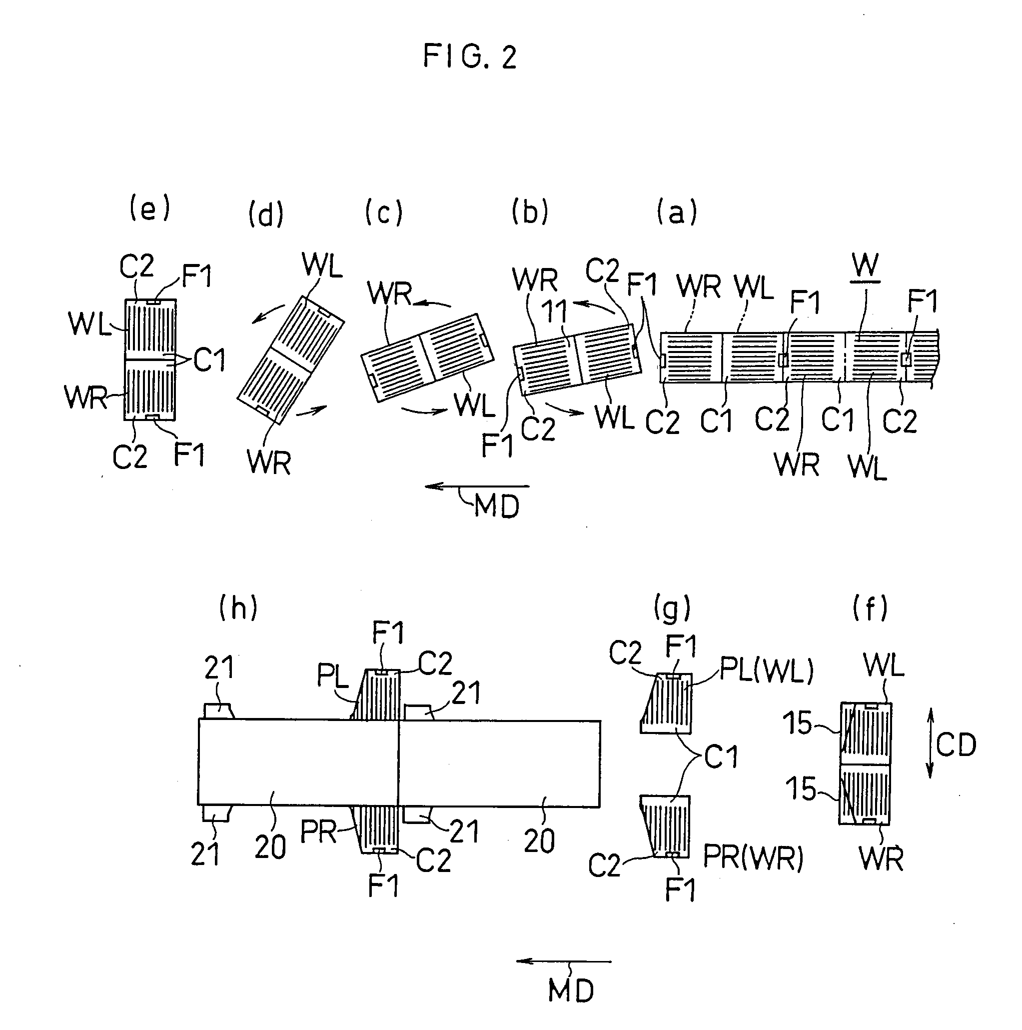
[0084] FIGS. 1 to 3 show the first embodiment.
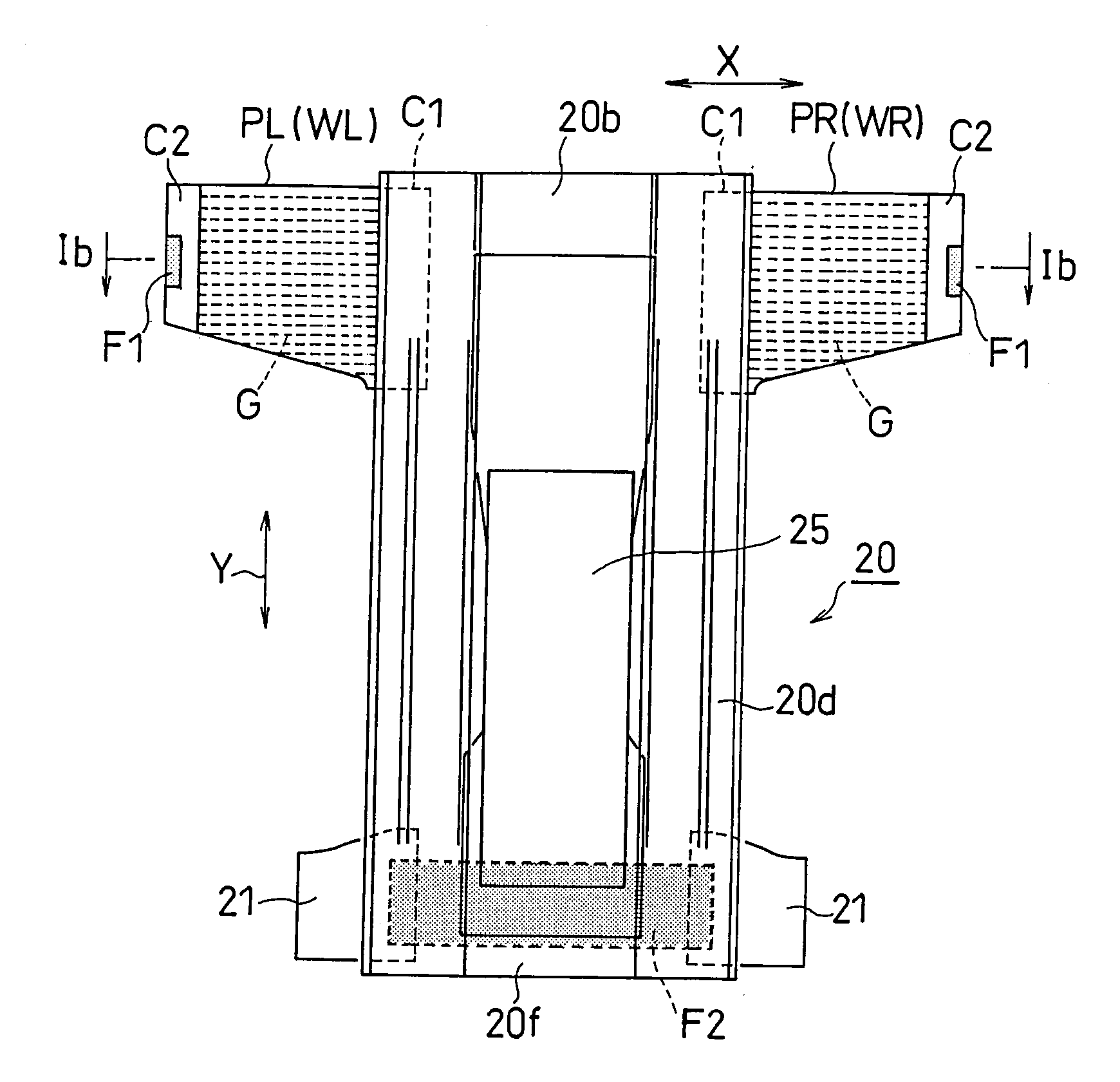
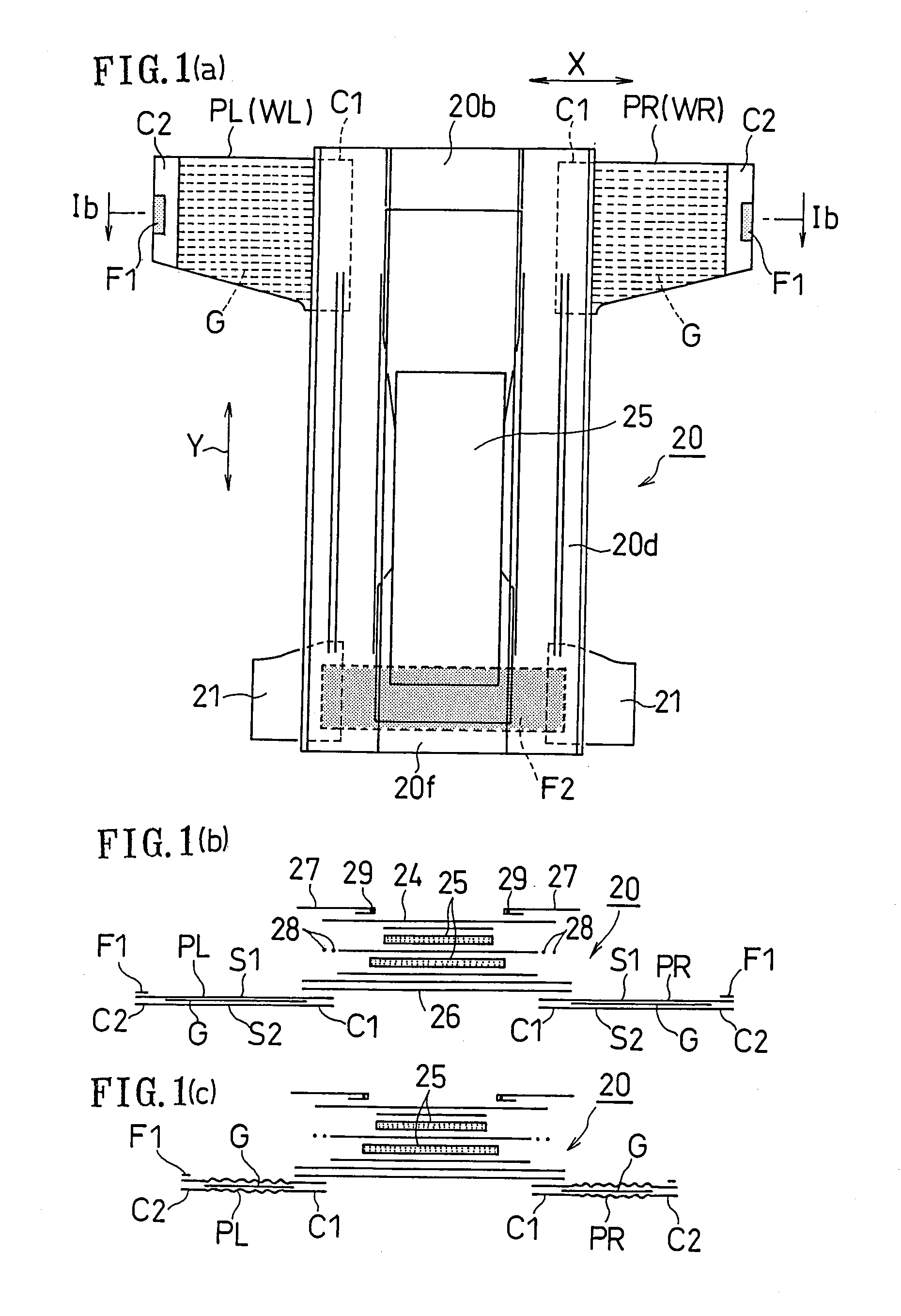
[0085] FIGS. 1(a) to 1(c) show an example of a disposable diaper of the first embodiment (an example of a worn article). FIG. 1(a) is a plan view showing a diaper being unfolded and extended, and FIG. 1(b) is a cross-sectional view taken along line Ib-Ib of FIG. 1(a).
[0086] As shown in FIG. 1(a), the diaper includes an absorbent main body portion 20, a pair of side panels PL and PR affixed to the main body portion 20, and a pair of tab members 21 and 21 affixed to the main body portion 20.
[0087] The main body portion 20, when worn, covers a front torso area (abdominal area), a crotch area and a rear torso area (back area) of the wearer. Corresponding to these areas, the main body portion 20 includes a front torso portion (abdominal portion) 20f, a crotch portion 20d and a rear torso portion (back portion) 20b.
[0088] Side Panels PL and PR:
[0089] When worn, the side panels PL and PR are each positioned between the front...
modified embodiment
[0134] Another method for obtaining a diaper of the first embodiment as described above will now be described.
[0135]FIGS. 4 and 5 show a modification of the embodiment.
[0136] As shown in (a) of FIG. 4, after the first touch fastener F1 is bonded to the second non-contractile portion C2, the laminate W is cut (slit) along a generally straight cut-off line extending in the flow direction MD. Thus, the laminate W is divided into the first and second laminates W1 and W2, which are separated from each other in the width direction CD (the direction generally perpendicular to the flow direction MD). Then, the first and second laminates W1 and W2 are spaced apart from each other in the width direction CD. The first touch fastener F1 may be bonded to each of the laminates W1 and W2 after the slitting process. After the spacing process, the two slit laminates W1 and W2 are cut off at a predetermined interval in the flow direction MD, i.e., repeatedly cutting off a tip portion of each of the...
second embodiment
[0146]FIGS. 6 and 7 show the second embodiment.
[0147] In the above-described first embodiment, a trimming process is performed when producing the cut panels to remove the unnecessary portions 15. The second embodiment and subsequent embodiments are directed to methods for producing cut panels that do not require the trimming process (i.e., methods without loss).
[0148] As shown in FIG. 6, in the side panels PL1 and PR1 (PL2 and PR2) of the second embodiment, the second non-contractile portion C2 is cut in a slant direction with respect to the Y direction. Other than this, the embodiment is similar to the first embodiment. Therefore, the same or like elements corresponding to those of the first embodiment will be denoted by the same reference numerals as the first embodiment and will not be further described below.
[0149] Production steps will now be described with reference to FIG. 7.
[0150] As shown in (a) of FIG. 7, after the first touch fastener F1 is bonded to the second non-co...
PUM
| Property | Measurement | Unit |
|---|---|---|
| Angle | aaaaa | aaaaa |
| Force | aaaaa | aaaaa |
| Flow rate | aaaaa | aaaaa |
Abstract
Description
Claims
Application Information
 - R&D
- Intellectual Property
- Life Sciences
- Materials
- Tech Scout
- Unparalleled Data Quality
- Higher Quality Content
- 60% Fewer Hallucinations
Browse by: Latest US Patents, China's latest patents, Technical Efficacy Thesaurus, Application Domain, Technology Topic, Popular Technical Reports.
© 2025 PatSnap. All rights reserved.Legal|Privacy policy|Modern Slavery Act Transparency Statement|Sitemap|About US| Contact US: help@patsnap.com


