
Steering systems, steering and speed coordination systems, and associated vehicles

a technology of steering system and steering linkage, which is applied in the field of steering system and steering speed coordination system, and associated vehicles, can solve the problems of confusing the user's steering lever, affecting and not providing correct steering, so as to reduce the speed of the vehicle

Active Publication Date: 2007-06-28
MTD PRODUCTS
View PDF62 Cites 53 Cited by
  • Summary
  • Abstract
  • Description
  • Claims
  • Application Information

AI Technical Summary

Benefits of technology

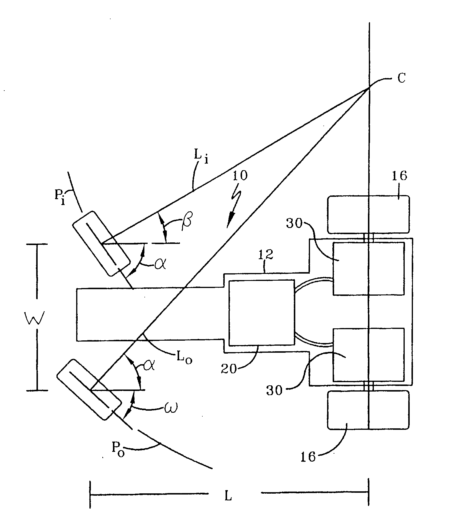
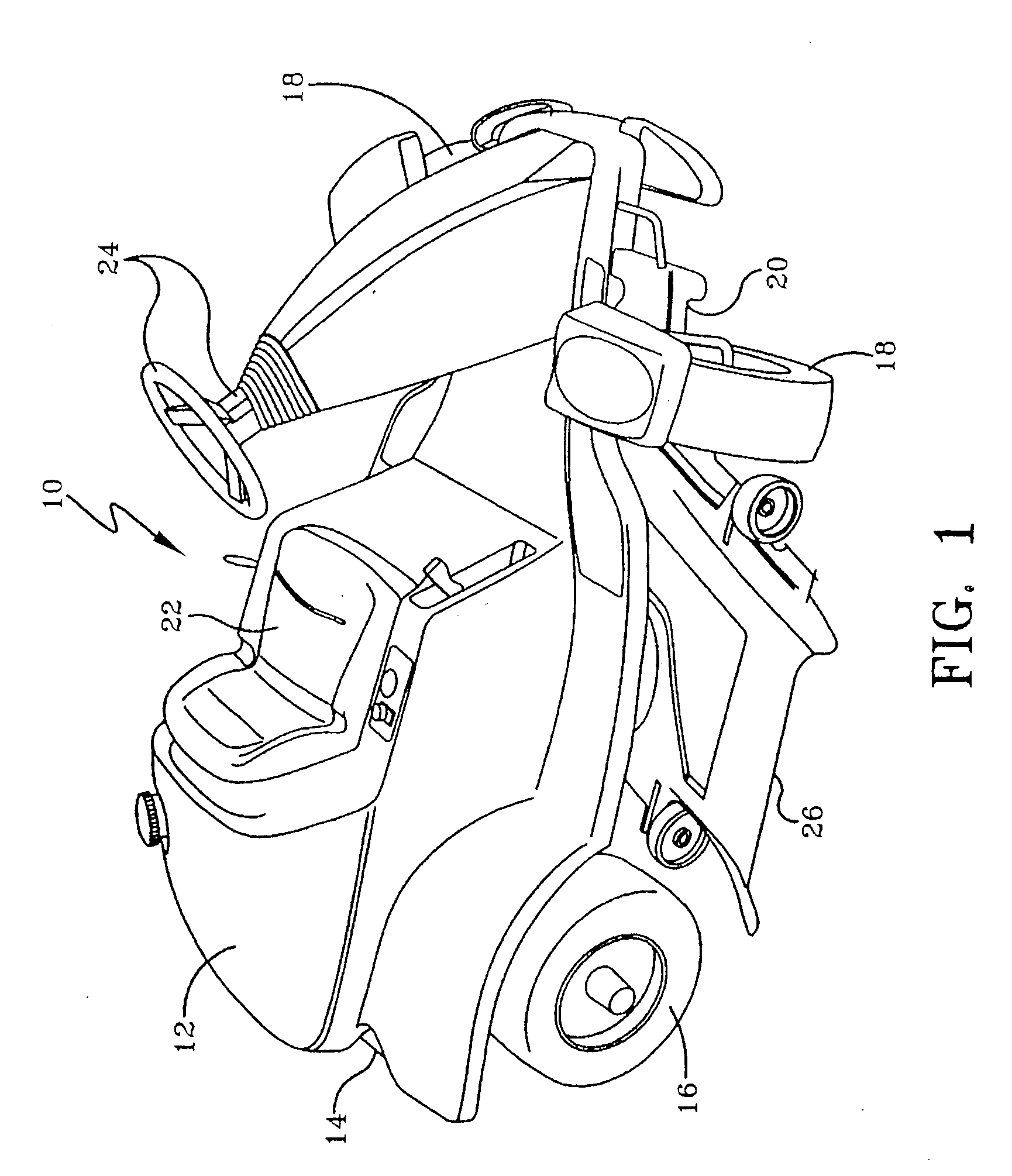
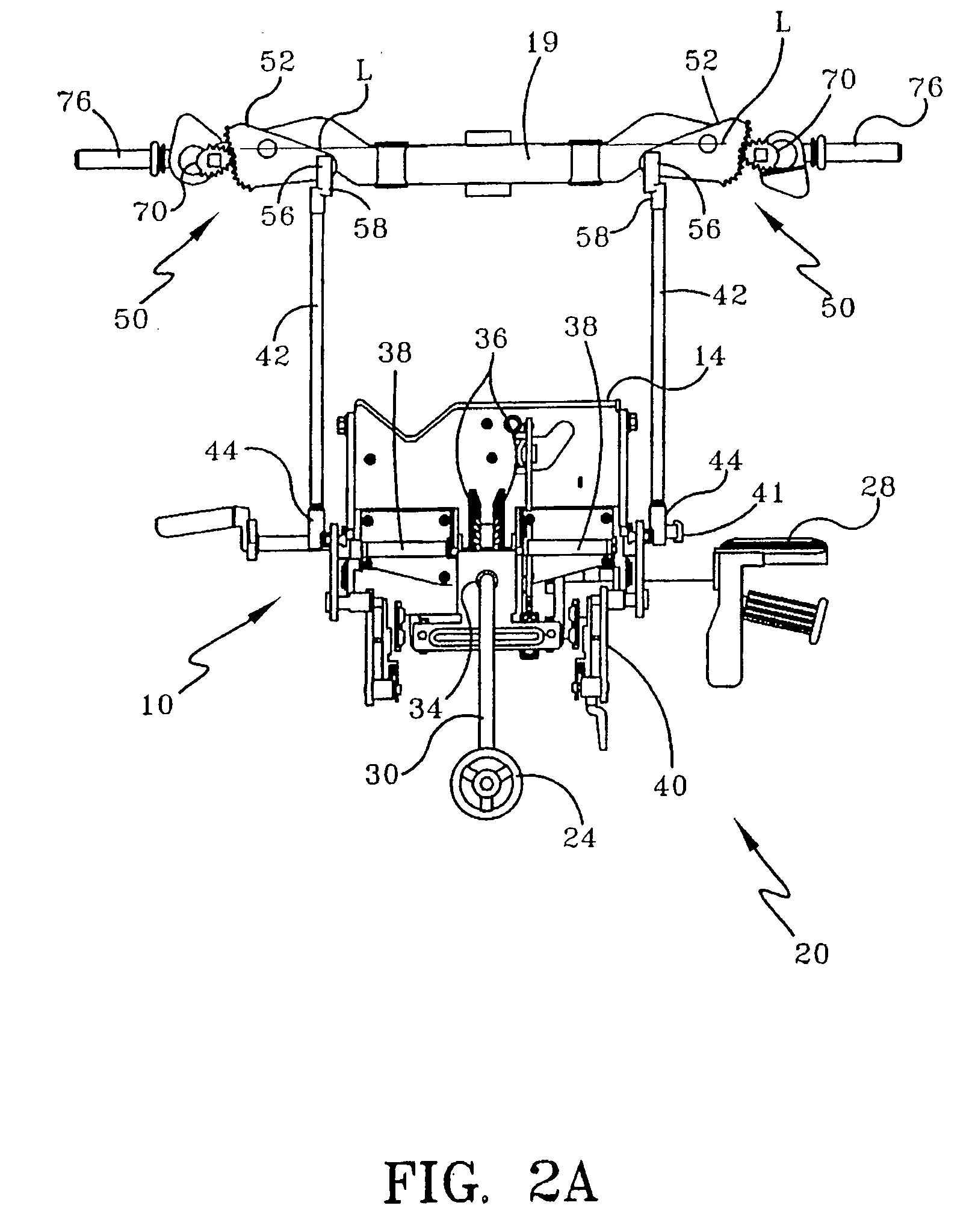
[0016] In a broad respect, the invention relates to vehicles that are capable of making a low- to zero-radius turn (e.g., a small radius turn) using the independent rotation of drive wheels and by turning the non-driving wheel or wheels with a steering input device (in some embodiments, the driving wheels may also be capable of being turned). This may be accomplished using a steering system, a speed control system and an integration device (together, a control system) that are configured to work together to provide correct steering in forward and reverse, and, in some embodiments, to reduce the speed of the vehicle (specifically the outboard drive wheel) when it enters a sufficiently extreme turn (e.g., one in which the ground engaging wheel can be turned no further) under constant speed input.

Problems solved by technology

Some users find these levers confusing because they control both vehicle speed and direction.
However, some of these vehicles do not provide correct steering when the vehicle is in reverse.
One problem with using caster wheels as non-steerable front wheels on ZTR vehicles is noticeable when driving on the side of a hill.
This may cause the portion of the vehicle supported by the caster wheels to turn downhill against the operator's wishes.
Additionally, when attempting to turn the ZTR vehicle uphill, the drive wheels may loose traction as the operator tries to produce the torque required to get the castor wheels pointed in the uphill direction.
For example, the Davis patent device is not equipped with a system that can reduce the speed of the outboard drive wheel of a vehicle entering an extreme turn at a constant speed input.
These patents disclose the use of caster wheels, and do not disclose the use of steerable front wheels.
U.S. Pat. No. 6,152,248 discloses the use of a non-circular gear pair in the steering of a vehicle, but that gear pair does not control the turning of a non-driving wheel.

Method used


Image

  • Steering systems, steering and speed coordination systems, and associated vehicles
  • Steering systems, steering and speed coordination systems, and associated vehicles
  • Steering systems, steering and speed coordination systems, and associated vehicles

Examples


embodiment

Worm Embodiment

[0131] Referring now to FIGS. 17-20, an alternate embodiment for integrating the steering input from the steering input device 24 and the speed input from the speed input device 28 is illustrated. As in the embodiment above, the drive units (not shown) are coupled to a linkage assembly which includes a pair of drive rods 104A pivotally coupled to pintle links (not shown). This embodiment illustrates the drive rod 104A as having a bell crank 149 disposed at one end (and which can be coupled to a bell crank disposed on another drive rod (not shown)) to accommodate the orientation of the transmission drive unit.

[0132]FIG. 17 shows the speed input shaft 110 coupled to two speed cams 112A via a second speed shaft 115A. Rotation of the speed input shaft 110 causes rotation of the second speed shaft 115A, which in turn rotates the speed cams 112A. The speed cams 112A have a substantially similar shape and substantially similar speed slot 119A as the speed cams 112 described...


PUM


Abstract

In a broad respect, vehicles that are capable of making a low- to zero-radius turn using the independent rotation of drive wheels and by turning the non-driving steerable structure or structures (such as wheels) with a steering input device (in some embodiments, the driving wheels also may be capable of being turned). This may be accomplished using a steering system, a speed control system and an integration device (together, a control system) that are configured to work together to provide correct steering in forward and reverse, and, in some embodiments, to reduce the speed of the outboard drive wheel of the vehicle when it enters an extreme turn under constant speed input. Different systems configured for use in such vehicles are included.

Description

CROSS-REFERENCE(S) TO RELATED APPLICATION(S) [0001] This application claims priority to U.S. Provisional Patent Application Ser. No. 60 / 701,716, filed Jul. 22, 2005, U.S. Provisional Patent Application Ser. No. 60 / 710,231, filed Aug. 22, 2005, and the U.S. Provisional Patent Application Ser. No. 60 / 731,593, filed on Oct. 26, 2005 in the names of Axel Schaedler, Hans Hauser, Rick Ruebusch, Ian David Cornwell, and Chris Greenwood and titled Steering Systems, Steering and Speed Coordination Systems, and Associated Vehicles. The contents of all three provisional applications are incorporated by reference.BACKGROUND [0002] 1. Field of the Invention [0003] The invention relates generally to vehicles that have low to zero turning radius capability. Zero turning radius vehicles are often described as ZTR vehicles. However, this name has also been used to described vehicles capable of a turning radius that is not precisely zero. More specifically, the invention relates to steering systems, s...

Claims


Application Information

Patent Timeline
IPC IPC(8): B62D11/24
CPCB60W10/10B60W10/20B60W30/045B62D7/08B62D7/09B62D9/00B62D11/006B62D11/24B60K17/00B62D1/04B62D3/02
Inventor SCHAEDLER, AXELHAUSER, HANSRUEBUSCH, RICKCORNWELL, IAN DAVIDGREENWOOD, CHRISTOPHER JOHN
Owner MTD PRODUCTS
Learn More