Belt-conveyor device and image forming apparatus

a technology of conveying belt and image forming apparatus, which is applied in the direction of electrographic process apparatus, instruments, optics, etc., can solve the problems of reducing image quality, transfer belt is likely to meander, and image quality reduction

Inactive Publication Date: 2007-06-28
RICOH KK
View PDF10 Cites 32 Cited by
  • Summary
  • Abstract
  • Description
  • Claims
  • Application Information

AI Technical Summary

Problems solved by technology

The meander of the transfer belt causes a relative position displacement of each toner image and a reduction in the image quality.
However, it is necessary to detect a belt position in the steering system, a transfer belt is likely to meander unless an angle of inclination of a steering roller is set based on a grasped correct belt position.
As described above, when printing starts while the transfer belt is meandering, relative position displacement occurs in toner images of yellow, magenta, cyan, and black, which causes a reduction in image quality.
Furthermore, when meandering of the transfer belt does not converges for a long time, it takes long time to turn on an image forming apparatus or to become a printing possible condition from an operation of an image forming apparatus recovering from error, thereby causing a reduction in printing efficiency.
When the converging time of the meander velocity is long, it takes long time to turn on an image forming apparatus or to become a printing possible condition from an operation of an image forming apparatus recovering from error, thereby causing a reduction in printing efficiency.
Under a condition of not converging meander velocity, when stops of a transfer belt due to error occurrence are consecutively repeated many times and meander correction generated by activation of the transfer belt is not completed, another meander is generated, leading to an accumulation of the meander amount.
As a result, durability of the transfer belt is considerably reduced, for example, the transfer belt comes into contact with a frame of a belt-conveyor device and is damaged.

Method used


Image

  • Belt-conveyor device and image forming apparatus
  • Belt-conveyor device and image forming apparatus
  • Belt-conveyor device and image forming apparatus

Examples


Embodiment Construction

[0027]Exemplary embodiments of the present invention will be explained below with reference to the accompanying drawings.

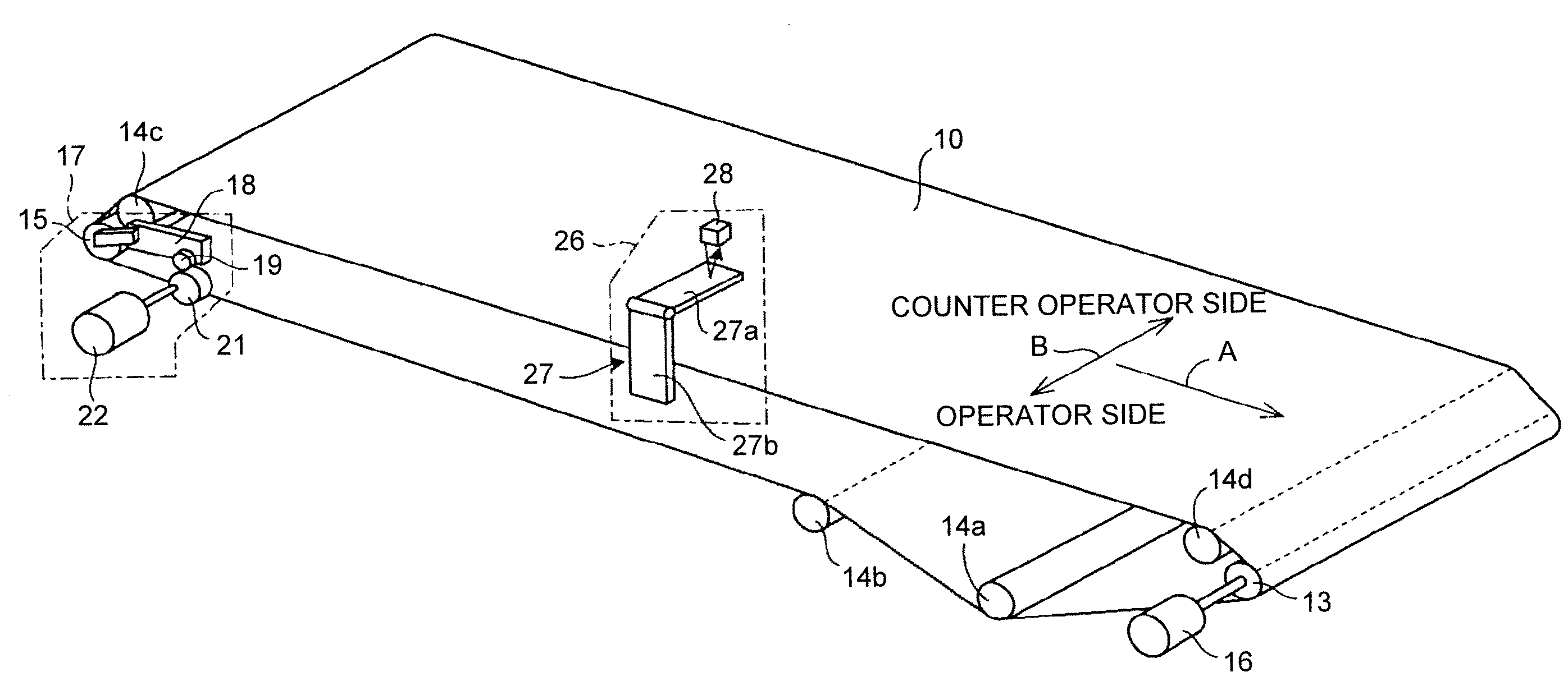
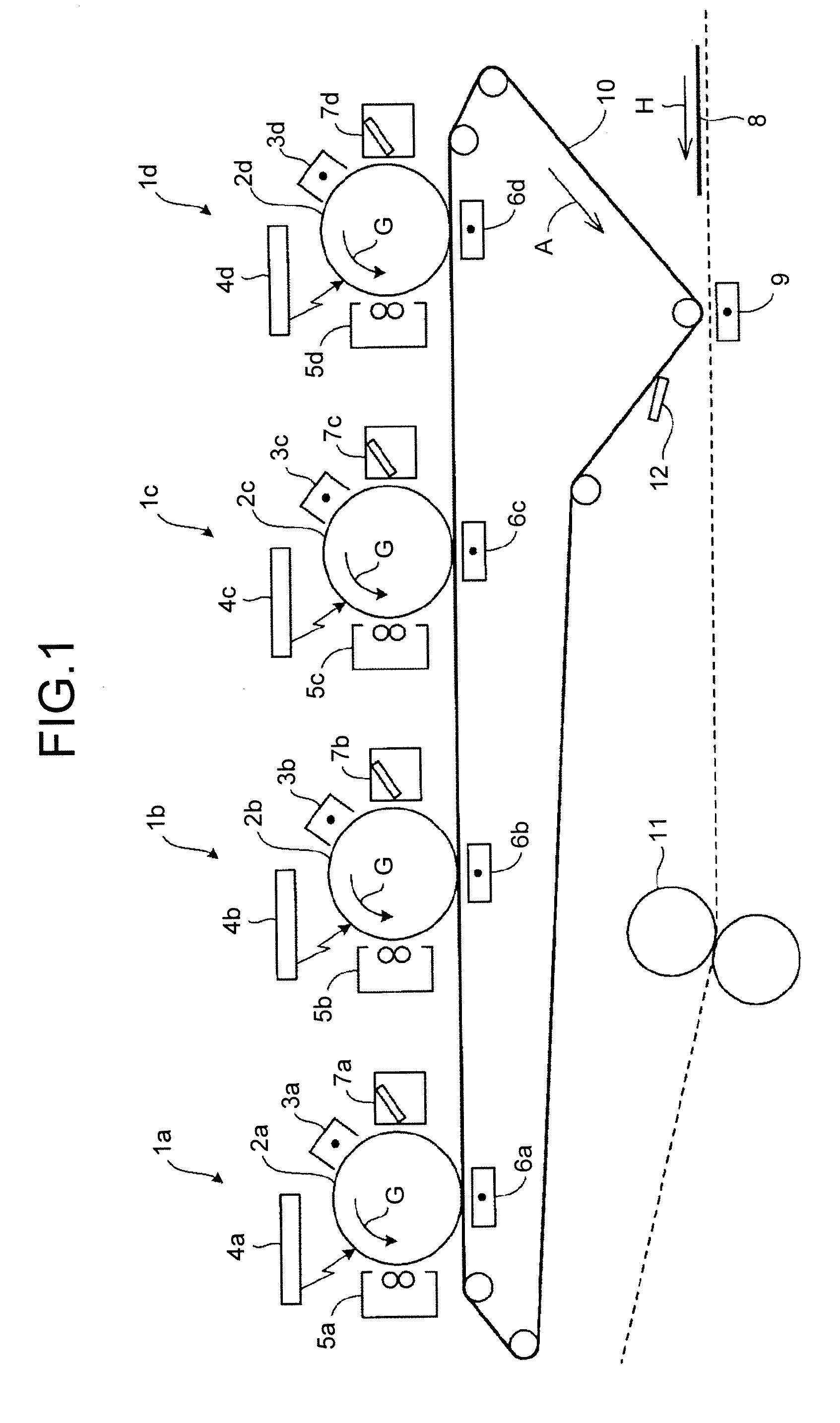
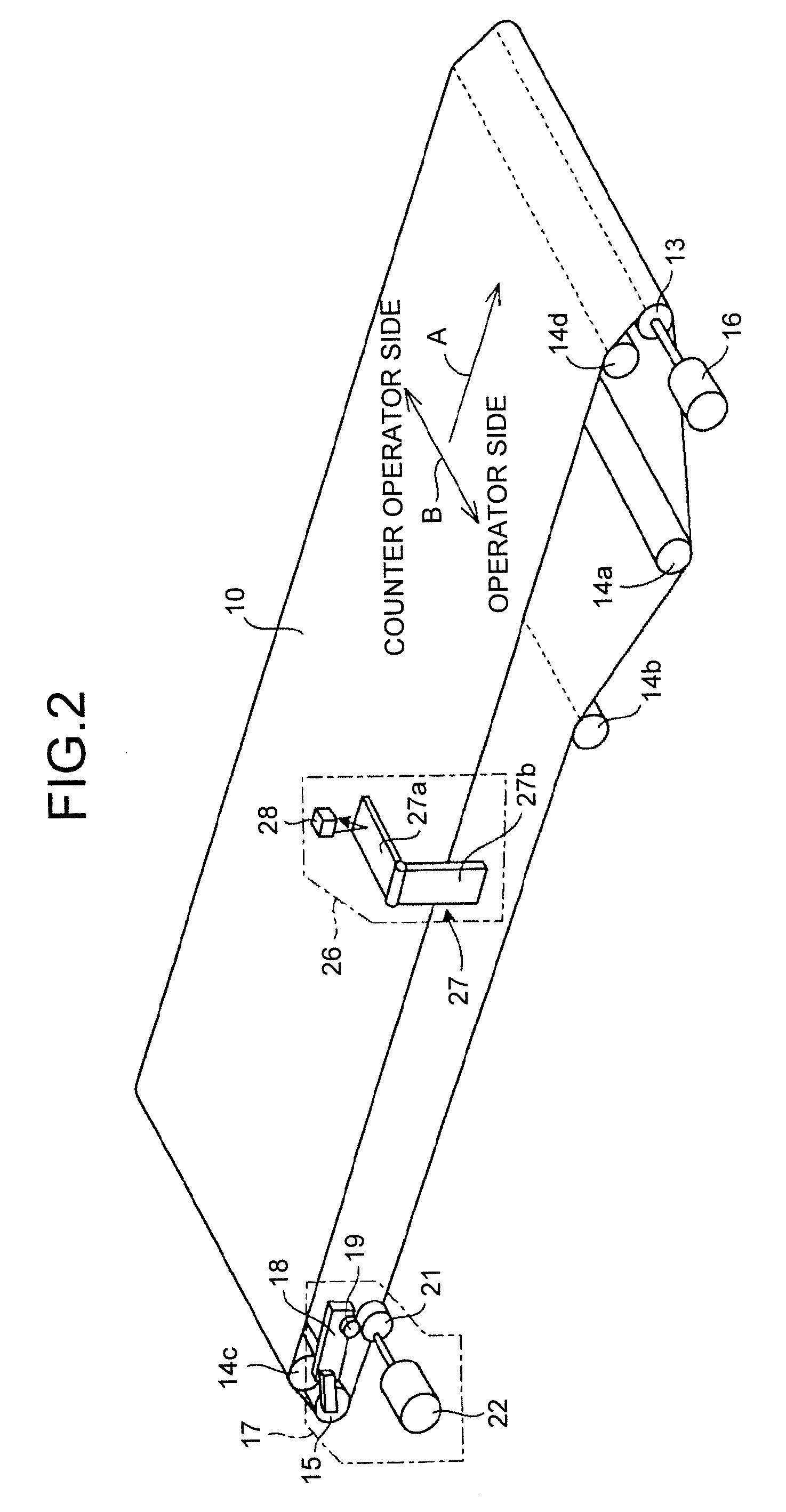
[0028]FIG. 1 outlines a four-full-color image forming apparatus according to an embodiment of the present invention. The image forming apparatus includes four image forming units 1a, 1b, 1c, 1d arranged in the travelling direction of a transfer belt 10. The image forming unit 1a includes a photoconductive drum 2a, a drum charging device 3a, an exposure device 4a, a developing device 5a, a transfer device 6a, and a cleaning device 7a. The image forming units 1b, 1c, and 1d have the same structure as the image forming unit 1a. Thus, “b”, “c”, and “d” are utilized instead of “a” of the last letter of the sign in each component of the image forming unit 1a in FIG. 1 and each corresponding component in the image forming units 1b, 1c, and 1d is indicated and the explanation is omitted.

[0029]The image forming units 1a to 1d form different-color images, for example, the i...


PUM


Abstract

A belt-conveyor device includes a detecting unit that detects a belt position in a width direction of the endless belt for a plurality of times within more than a cycle of the endless belt, the width direction being a direction orthogonal to direction of travel of the endless belt; an average calculating unit that calculates an average belt position from the belt positions detected by the detecting unit; a storing unit that stores therein a plural sets of correction values and belt positions; and a meander correcting unit that corrects meander of the endless belt based on a correction value that corresponds with the average belt position in the storing unit.

Description

CROSS-REFERENCE TO RELATED APPLICATIONS[0001]The present document incorporates by reference the entire contents of Japanese priority document, 2005-380240 filed in Japan on Dec. 28, 2005.BACKGROUND OF THE INVENTION[0002]1. Field of the Invention[0003]The present invention relates to a belt-conveyor device and an image forming apparatus that includes the belt-conveyor device.[0004]2. Description of the Related Art[0005]A tandem system is widely employed in color image forming apparatuses such as color printers and color copiers. In the tandem system, a plurality of photoconductive drums are arranged in the travel direction of an endless transfer belt, a toner image is formed by adhering toners of different colors such as yellow, magenta, cyan, and black on an electrostatic latent image formed on each of the photoconductive drums, and the toner image of each color is transferred to the transfer belt in turn. A transfer belt driven by a belt-conveyor device sometimes gets biased or som...

Claims


Application Information

Patent Timeline
Patent Type & Authority Applications(United States)
IPC IPC(8): B65G39/16
CPCG03G15/0131G03G2215/00143G03G2215/0119G03G2215/0158G03G15/1615
Inventor TAO, SATORUSANO, YOSHIHIKOSAITO, SUSUMUOOHARA, SHUNICHIFURUYA, NOBUYUKI
Owner RICOH KK
Why Eureka
Try Eureka