Plug connector

a plug connector and connector technology, applied in the direction of electrical apparatus, connection, coupling device connection, etc., can solve the problems of unstable signals transmitted by the plug connector, and achieve the effects of improving the elasticity of the soldering portion, stable signals transmitted by the plug connector, and easy soldering

Active Publication Date: 2016-09-27
CHENG UEI PRECISION IND CO LTD
View PDF8 Cites 21 Cited by
  • Summary
  • Abstract
  • Description
  • Claims
  • Application Information

AI Technical Summary

Benefits of technology

[0008]As described above, the thickness of the soldering portion of the middle shielding piece is thinner than the thicknesses of the base plate and the lateral arms of the middle shielding piece for improving an elasticity of the soldering portion, so the soldering portion is easily soldered on a circuit board. As a result, signals transmitted by the plug connector are stable.

Problems solved by technology

As a result, signals transmitted by the plug connector are unstable.

Method used


Image

  • Plug connector
  • Plug connector
  • Plug connector

Examples


Embodiment Construction

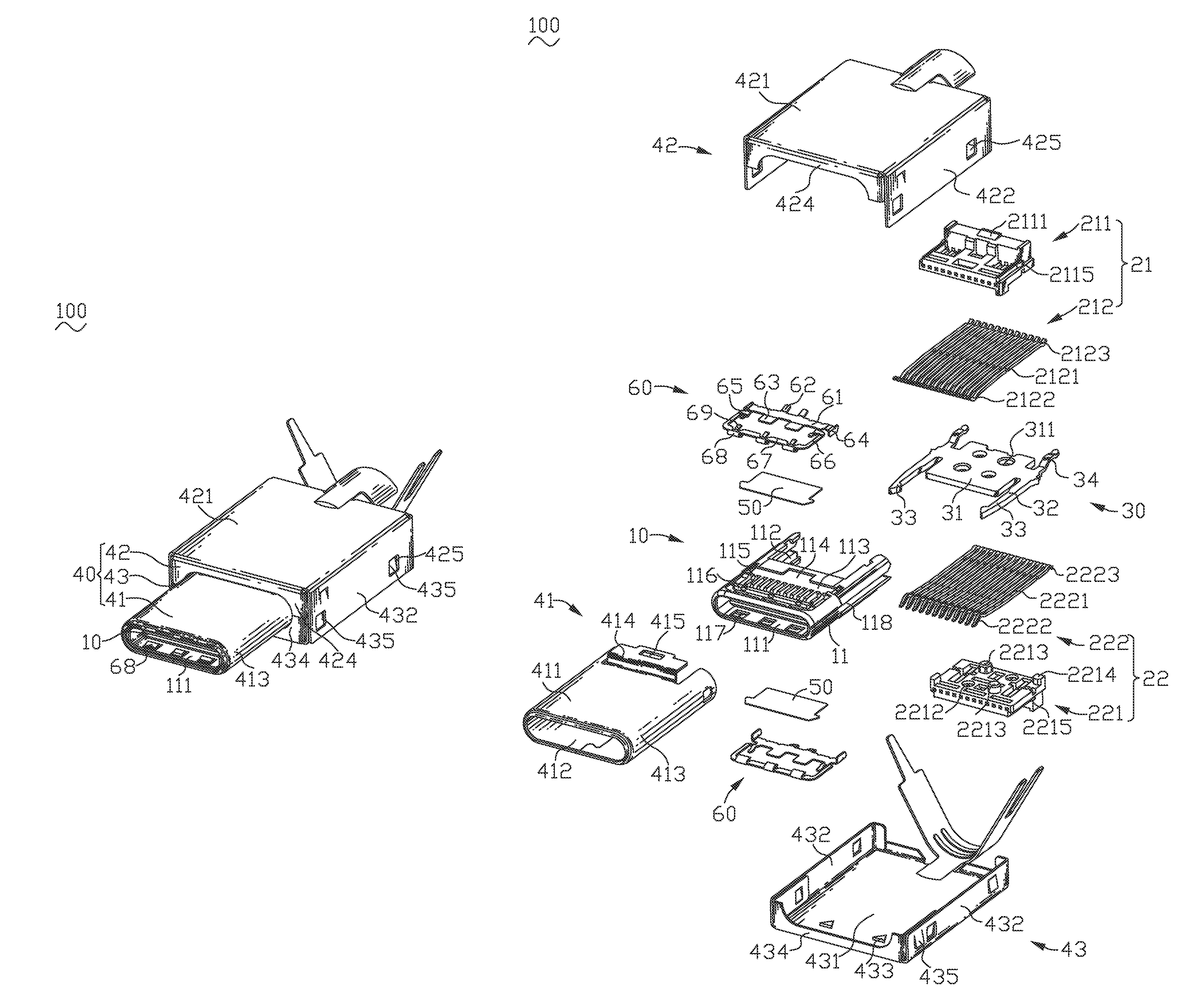
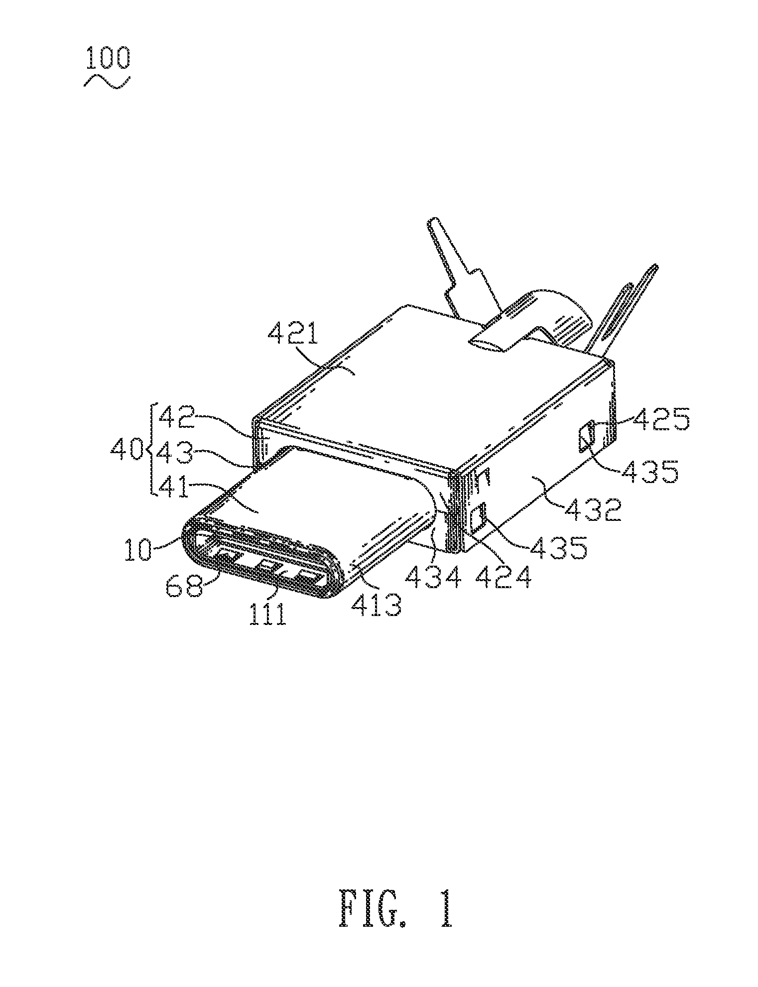
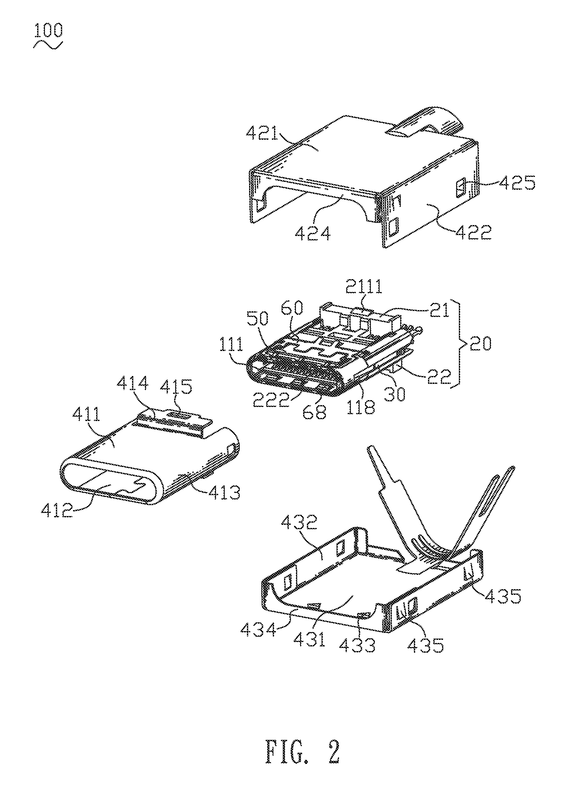
[0017]With reference to FIG. 1, FIG. 2 and FIG. 4, a plug connector 100 in accordance with the present invention is shown. The plug connector 100 includes an insulating housing 10, a terminal module 20, a middle shielding piece 30, a shielding shell 40, two insulation films 50 and two ground pieces 60. The plug connector 100 is a USB 3.1 plug connector.

[0018]Referring to FIG. 3 to FIG. 7, the insulating housing 10 has a base body 11. A front end of the base body 11 defines an insertion chamber 111 penetrating through a middle of a front surface of the base body 11. The insertion chamber 111 is matched with an insertion portion (not shown) of a receptacle connector (not shown). A rear end of the base body 11 defines an assembling groove 112 vertically penetrating through a middle of the rear end of the base body 11 and further penetrating through a rear surface of the base body 11. A middle of a front wall of the assembling groove 112 is recessed frontward to form a fastening slot 11...


PUM


Abstract

A plug connector includes an insulating housing, a terminal module, a middle shielding piece, and a shielding shell surrounding the insulating housing and the terminal module. The terminal module includes a first terminal module and a second terminal module. The middle shielding piece is mounted between the first terminal module and the second terminal module. The terminal module together with the middle shielding piece is assembled to the insulating housing. The middle shielding piece has a base plate. Two portions of two opposite sides of the base plate extend outward and then extend frontward to form two lateral arms. An upper end of a rear surface of each of the lateral arms meanders rearward to form a soldering portion projecting out of the insulating housing. A thickness of the soldering portion is thinner than thicknesses of the base plate and the lateral arms.

Description

BACKGROUND OF THE INVENTION[0001]1. Field of the Invention[0002]The present invention generally relates to a plug connector, and more particularly to a USB 3.1 plug connector.[0003]2. The Related Art[0004]At present, USB 3.1 specifications are the newest USB specifications. The USB 3.1 specifications are launched by Intel company and other major companies. A data transmission speed of a USB 3.1 connector can be promoted to 10 Gbps, and a maximum power supply capability of the USB 3.1 connector is promoted to 100 W. Comparing with current USB technologies, a more efficient data coding system is applied in a USB 3.1 technology, and more than doubled throughput rates of valid data is provided. The USB 3.1 technology is completely compatible with current USB connectors and cables. Interface types of the USB 3.1 connectors are Type-A, Type-B and Type-C. In order to cater to development demand of thinner devices, new USB 3.1 Type-C interfaces need to be developed.[0005]A current plug conn...

Claims


Application Information

Patent Timeline
Patent Type & Authority Patents(United States)
IPC IPC(8): H01R13/6593H01R13/6585
CPCH01R13/6585H01R13/5202H01R13/6581
Inventor CHIANG, CHIH-HSIENYU, SHENG-NAN
Owner CHENG UEI PRECISION IND CO LTD
Why Eureka
Try Eureka