Optical deflector including piezoelectric sensor incorporated into outermost piezoelectric cantilever

a piezoelectric actuator and optical deflector technology, applied in the field of optical deflectors, can solve the problems of reducing the area of the drive elements in the piezoelectric actuator, and reducing so as to increase the width of the piezoelectric cantilever, reduce the resistance of the wiring line, and increase the deflection angle of the optical deflector

Active Publication Date: 2013-11-14
STANLEY ELECTRIC CO LTD
View PDF22 Cites 21 Cited by
  • Summary
  • Abstract
  • Description
  • Claims
  • Application Information

AI Technical Summary

Benefits of technology

[0013]Since the piezoelectric sensor is incorporated into the outermost piezoelectric cantilever, the provision area of the drive portion of the piezoelectric cantilevers in the piezoelectric actuators is increased so that the rocking forces of the piezoelectric actuators are strengthened, thus increasing the deflection angles of the optical deflector. Also, since wiring lines connected to the piezoelectric cantilevers are shortened, the resistance of the wiring lines can be decreased. Further, since the width of the piezoelectric cantilevers can be increased, and also, the spacing therebetween can be increased, the high frequency sense signal from the piezoelectric sensor can be detected due to no crosstalk. As a result, it is possible to accurately control the actual flexing amounts of the piezoelectric actuators by the feedback of the output signal of the piezoelectric sensor.

Problems solved by technology

In the above-described prior art two-dimensional optical deflector, however, since the sense elements are provided in the entire piezoelectric actuators, the provision area of the drive elements in the piezoelectric actuators is decreased so that the rocking forces of the piezoelectric actuators are weakened, thus decreasing the deflection angles of the optical deflector.
Therefore, the high frequency sense signals from the sense elements cannot be detected due to their crosstalk.
As a result, it is impossible to accurately control the actual flexing amounts of the piezoelectric actuators by the feedback of the output signals of the sense elements.

Method used


Image

  • Optical deflector including piezoelectric sensor incorporated into outermost piezoelectric cantilever
  • Optical deflector including piezoelectric sensor incorporated into outermost piezoelectric cantilever
  • Optical deflector including piezoelectric sensor incorporated into outermost piezoelectric cantilever

Examples


first embodiment

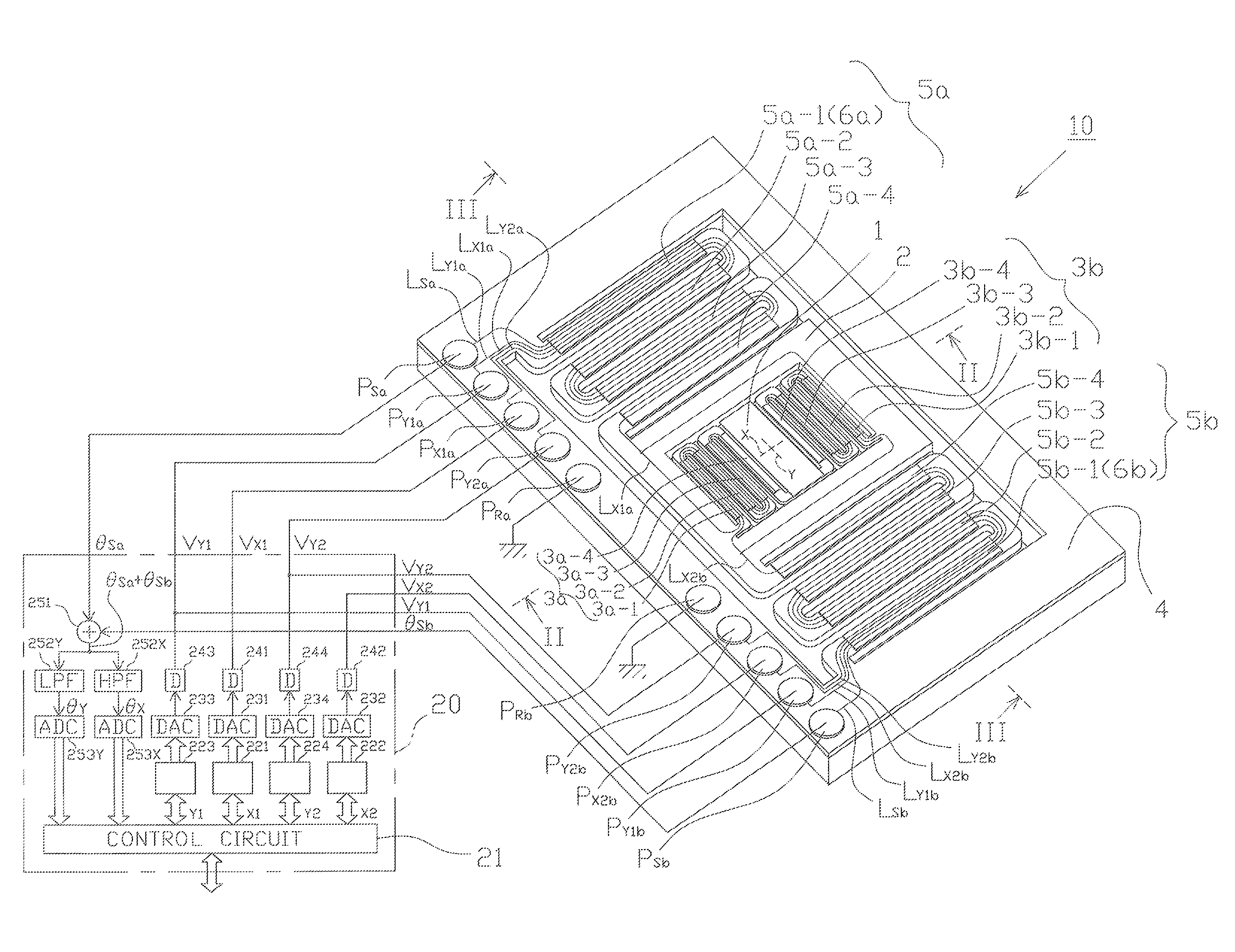
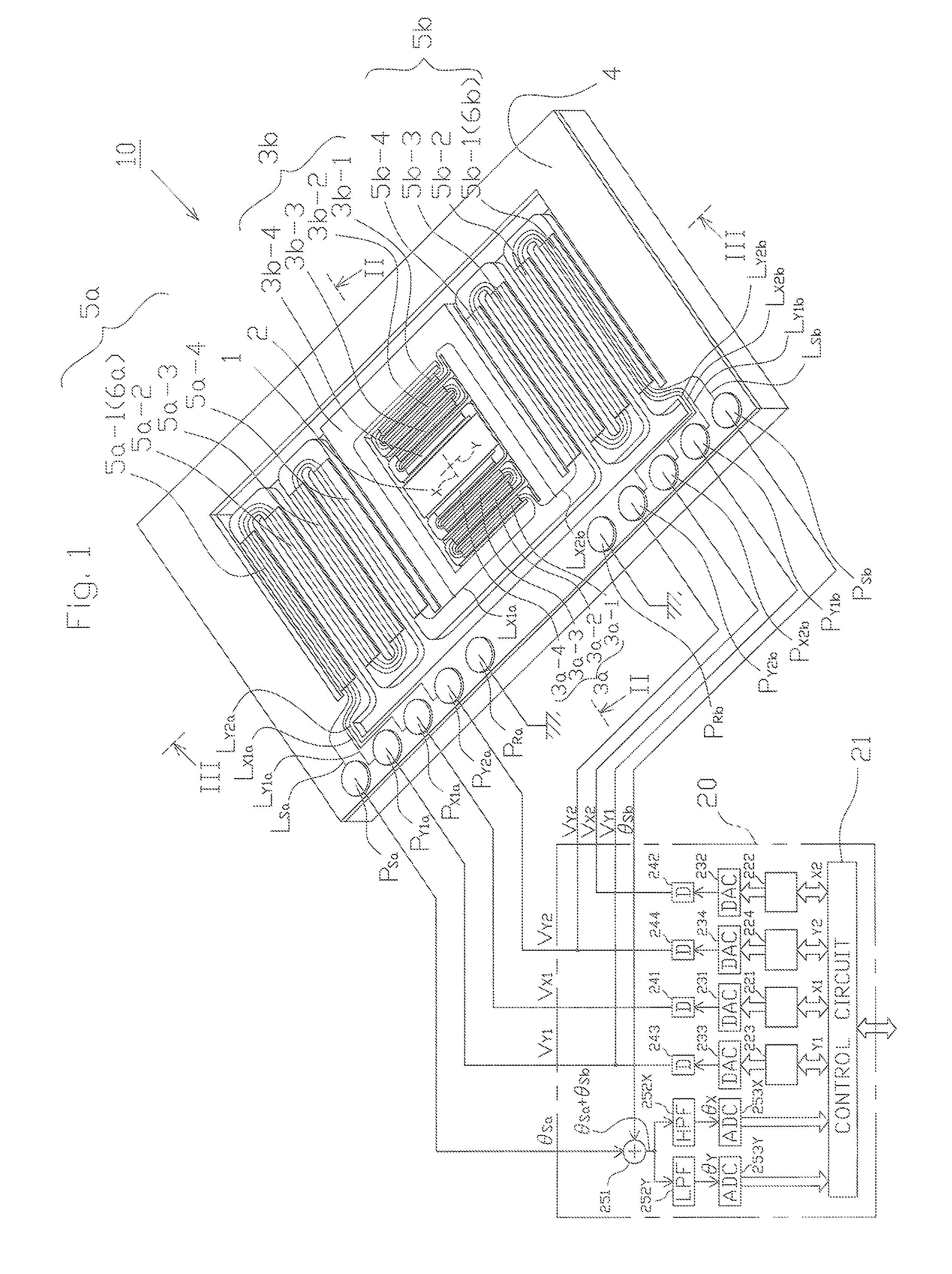
[0024]In FIG. 1, which illustrates the optical deflector according to the presently disclosed subject matter, reference numeral 10 designates a two-dimensional optical deflector, and 20 designates a driver for driving the two-dimensional optical deflector 10.

[0025]The optical deflector 10 is constructed by a rectangular mirror 1 for reflecting an incident light, a movable frame 2 surrounding the mirror 1 for supporting the mirror 1, a pair of meander-type inner piezoelectric actuators 3a and 3b fixed between the movable frame 2 and the mirror 1 and serving as cantilevers for rocking the mirror 1 with respect to an X-axis of the mirror 1, a support body 4 surrounding the movable frame 2, and a pair of meander-type outer piezoelectric actuators 5a and 5b fixed betweeen the support body 4 and the movable frame 2 and serving as cantilevers for rocking the mirror 1 through the movable frame 2 with respect to a Y-axis of the mirror 1 perpendicular to the X-axis.

[0026]Piezoelectric sensors...

second embodiment

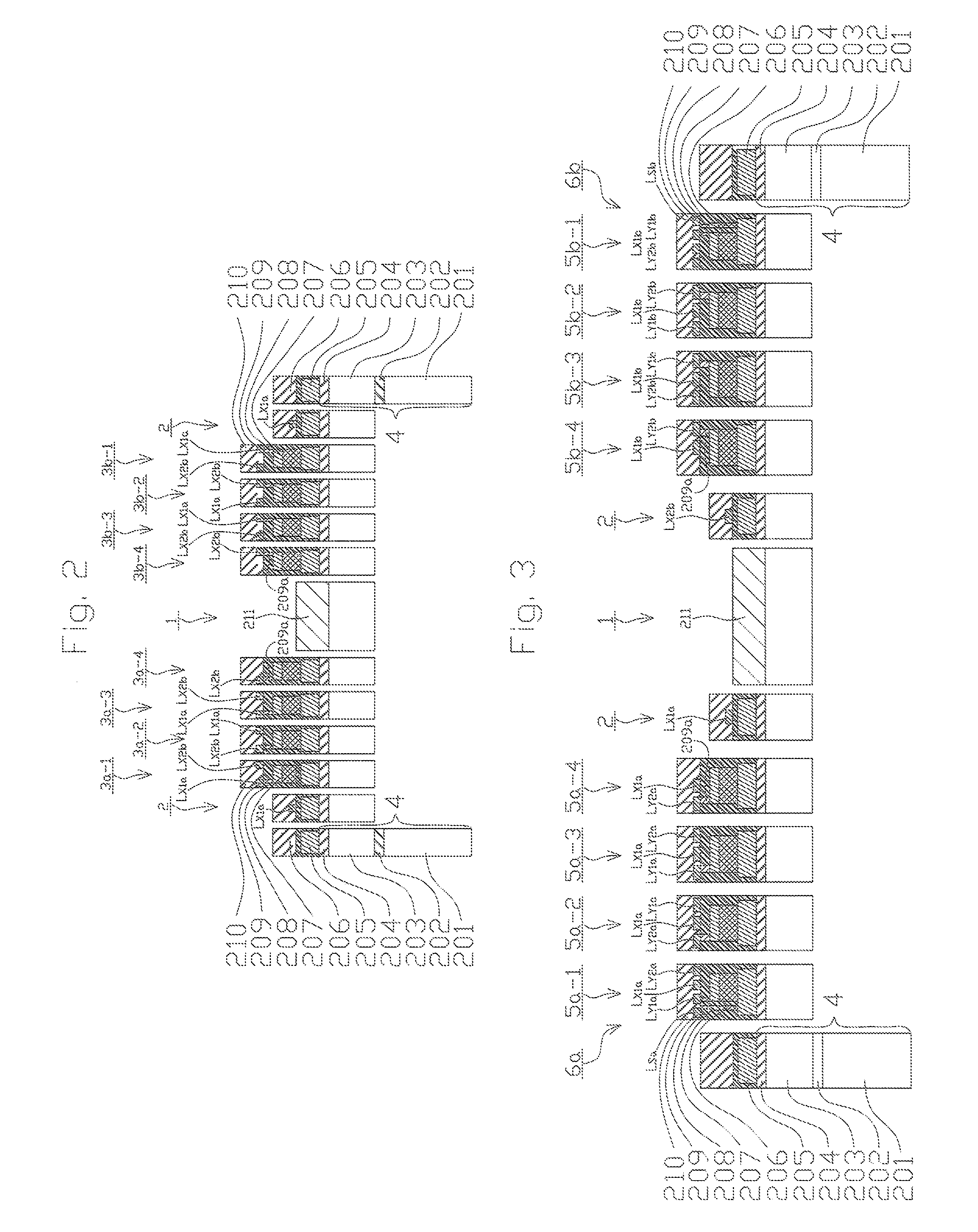
[0089]FIG. 8 illustrates the two-dimensional optical deflector according to the presently disclosed subject matter, the cross-sectional views of the optical deflector 10 of FIG. 8 are similar to those of the two-dimensional optical deflector 10 of FIG. 1, and therefore, they are omitted.

[0090]In the optical deflector 10 of FIG. 8, the pair of the meander-type inner piezoelectric actuators 3a and 3b of FIG. 1 are replaced by a pair of torsion bars 7a and 7b and a pair of inner piezoelectric actuators 8a and 8b.

[0091]The meander-type inner piezoelectric actuators 3a and 3b of FIG. 1 are of a non-resonance type, but the inner piezoelectric actuators 8a and 8b associated with the torsion bars 7a and 7b of FIG. 8 are of a resonance type. That is, when the rocking frequency fX of the torsion-bar type inner piezoelectric actuators 8a and 8b is close to the natural frequency of a mechanically-vibrating system of the mirror 1 with respect to the X-axis depending upon the structure of the in...


PUM


Abstract

In an optical deflector including a mirror, a movable frame supporting the mirror, a first piezoelectric actuator for rocking the mirror with respect to a first axis of the mirror, a support body supporting the movable frame, and a second piezoelectric actuator for rocking the mirror through the movable frame with respect to a second axis of the mirror, at least one piezoelectric sensor is provided for sensing rocking vibrations of the mirror caused by the first and second piezoelectric actuators. The second piezoelectric actuator includes a pair of meander-type pieoelectric actuators opposite to each other with respect to the first axis. Each of the second meander-type piezoelectric actuators includes a plurality of piezoelectric cantilevers folded at every cantilever and connected from the support body to the movable frame in parallel with the first axis. The piezoelectric sensor is incorporated into an outermost one of the piezoelectric cantilevers.

Description

[0001]This application claims the priority benefit under 35 U.S.C. §119 to Japanese Patent Application No. JP2012-066894 filed on Mar. 23, 2012, which disclosure is hereby incorporated in its entirety by reference.BACKGROUND[0002]1. Field[0003]The presently disclosed subject matter relates to an optical deflector including sense elements (piezoelectric sensors).[0004]2. Description of the Related Art[0005]A prior art two-dimentsional optical deflector is constructed by a mirror, a movable frame surrounding the mirror for supporting the mirror, a pair of meander-type inner piezoelectric actuators fixed between the movable frame and the mirror and serving as cantilevers for rocking the mirror with respect to an X-axis of the mirror, a support body surrounding the movable frame, and a pair of meander-type outer piezoelectric actuators fixed between the support body and the movable frame and serving as cantilevers for rocking the mirror through the movable frame with respect to a Y-axis...

Claims


Application Information

Patent Timeline
Patent Type & Authority Applications(United States)
IPC IPC(8): G02B26/08
CPCG02B26/08G02B26/0858G02B26/101
Inventor AIMONO, TAKANORI
Owner STANLEY ELECTRIC CO LTD
Why Eureka
Try Eureka