Optical lens, camera module and electronic equipment

An optical lens and lens technology, which is applied in optics, optical components, instruments, etc., can solve the problems that affect the optical lens to capture object image information, limit the field of view, and limit the field of view of the optical lens, so as to reduce the sensitivity to changes in resolution Intensity, increase the relative illuminance, improve the effect of image quality

Active Publication Date: 2022-06-24
JIANGXI JINGCHAO OPTICAL CO LTD
View PDF3 Cites 3 Cited by
  • Summary
  • Abstract
  • Description
  • Claims
  • Application Information

AI Technical Summary

Problems solved by technology

However, the miniaturization of the optical lens will limit the field of view, which will limit the field of view of the optical lens and affect the information acquisition of the object image by the optical lens

Method used


Image

  • Optical lens, camera module and electronic equipment
  • Optical lens, camera module and electronic equipment
  • Optical lens, camera module and electronic equipment

Examples


no. 1 example

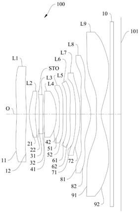
[0101] The schematic structural diagram of the optical lens 100 disclosed in the first embodiment of the present application is as follows: figure 1 As shown, the optical lens 100 includes a first lens L1, a second lens L2, a diaphragm STO, a third lens L3, a fourth lens L4, a fifth lens L5, a third lens L3, a fourth lens L4, a fifth lens L5, Six lenses L6, seventh lens L7, eighth lens L8, ninth lens L9, infrared filter 10. The materials of the first lens L1, the second lens L2, the third lens L3, the fourth lens L4, the fifth lens L5, the sixth lens L6, the seventh lens L7, the eighth lens L8 and the ninth lens L9 can be Refer to the above-mentioned specific implementation manners, and details are not repeated here.

[0102] Further, the first lens L1 has a positive refractive power, the second lens L2 has a positive refractive power, the third lens L3 has a negative refractive power, the fourth lens L4 has a positive refractive power, the fifth lens L5 has a positive refrac...

no. 2 example

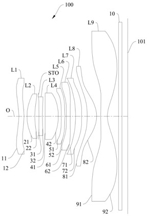
[0114] The schematic structural diagram of the optical lens 100 disclosed in the second embodiment of the present application is as follows: image 3 As shown, the optical lens 100 includes a first lens L1, a second lens L2, a diaphragm STO, a third lens L3, a fourth lens L4, a fifth lens L5, a third lens L3, a fourth lens L4, a fifth lens L5, Six lenses L6, seventh lens L7, eighth lens L8, ninth lens L9, infrared filter 10. The materials of the first lens L1, the second lens L2, the third lens L3, the fourth lens L4, the fifth lens L5, the sixth lens L6, the seventh lens L7, the eighth lens L8 and the ninth lens L9 can be Refer to the above-mentioned specific implementation manners, and details are not repeated here.

[0115] Further, the first lens L1 has a negative refractive power, the second lens L2 has a positive refractive power, the third lens L3 has a negative refractive power, the fourth lens L4 has a positive refractive power, the fifth lens L5 has a positive refra...

no. 3 example

[0126] The schematic structural diagram of the optical lens 100 disclosed in the third embodiment of the present application is as follows: Figure 5 As shown, the optical lens 100 includes a first lens L1, a second lens L2, a diaphragm STO, a third lens L3, a fourth lens L4, a fifth lens L5, a third lens L3, a fourth lens L4, a fifth lens L5, Six lenses L6, seventh lens L7, eighth lens L8, ninth lens L9, infrared filter 10. The materials of the first lens L1, the second lens L2, the third lens L3, the fourth lens L4, the fifth lens L5, the sixth lens L6, the seventh lens L7, the eighth lens L8 and the ninth lens L9 can be Refer to the above-mentioned specific implementation manners, and details are not repeated here.

[0127] Further, the first lens L1 has a negative refractive power, the second lens L2 has a positive refractive power, the third lens L3 has a negative refractive power, the fourth lens L4 has a positive refractive power, the fifth lens L5 has a negative refra...


PUM


Abstract

The invention discloses an optical lens, a camera module and electronic equipment, and the optical lens comprises a first lens with refractive power, a second lens with refractive power, a third lens with refractive power, a fourth lens with refractive power, a fifth lens and a sixth lens which are sequentially arranged from an object side to an image side along an optical axis, the object side surface and the image side surface of the second lens are respectively a convex surface and a concave surface; a third lens element with negative refractive power having a concave image-side surface; the object side surface and the image side surface of the fourth lens are convex surfaces; the object side surface and the image side surface of the fifth lens are respectively a concave surface and a convex surface; the object side surface and the image side surface of the sixth lens are concave surfaces; a seventh lens element with refractive power having a concave object-side surface; the image side surface of the eighth lens is a convex surface; the object side surface and the image side surface of the ninth lens are respectively a convex surface and a concave surface; the optical lens satisfies 0.3 lt; sD < 12 > / IMGHlt; and 0.5. With the adoption of the scheme, while the imaging quality is ensured, the optical system has the characteristics of miniaturization and large field angle.

Description

technical field [0001] The invention relates to the technical field of optical imaging, in particular to an optical lens, a camera module and an electronic device. Background technique [0002] With the advancement and development of technology, people have higher and higher requirements for the imaging capabilities of electronic equipment, and electronic equipment has shown a trend of miniaturization. This saves space for other components. However, the miniaturization of the optical lens will limit the field of view, thereby limiting the field of view of the optical lens and affecting the information capture of the object image by the optical lens. SUMMARY OF THE INVENTION [0003] The embodiment of the invention discloses an optical lens, a camera module and an electronic device, which can ensure the imaging quality and have the characteristics of miniaturization and large viewing angle. [0004] In order to achieve the above object, in the first aspect, the present in...

Claims


Application Information

Patent Timeline
Patent Type & Authority Applications(China)
IPC IPC(8): G02B13/06G02B13/18
CPCG02B13/0045G02B13/06
Inventor 龙鑫灿李明
Owner JIANGXI JINGCHAO OPTICAL CO LTD
Why Eureka
Try Eureka