Full-process automatic machining system for front shaft

A mechanical processing and whole-process technology, applied in the direction of metal processing machinery parts, metal processing equipment, manufacturing tools, etc., can solve the problems of low processing efficiency, small cutting force, small deflection angle, etc., to improve processing capacity and efficiency, improve Effect of deflection angle and cutting force

Pending Publication Date: 2020-11-24
HUBEI TRI RING AXLE
View PDF0 Cites 3 Cited by
  • Summary
  • Abstract
  • Description
  • Claims
  • Application Information

AI Technical Summary

Problems solved by technology

In the existing front-axis machining center, the tool deflection is completed by deflecting the cutter head, the deflection angle is small, limited, and the cutting force is small, and the processing efficiency is low

Method used


Image

  • Full-process automatic machining system for front shaft
  • Full-process automatic machining system for front shaft
  • Full-process automatic machining system for front shaft

Examples


Embodiment Construction

[0021] The present invention will be described in further detail below in conjunction with the accompanying drawings and specific embodiments, and the implementation scope of the present invention is not limited thereto.

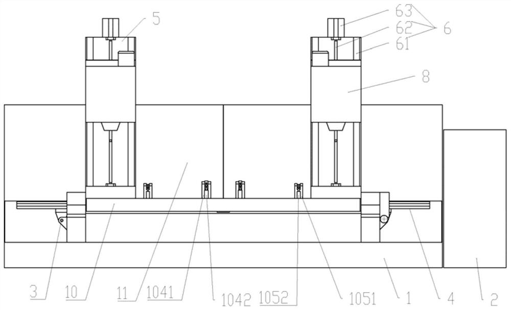
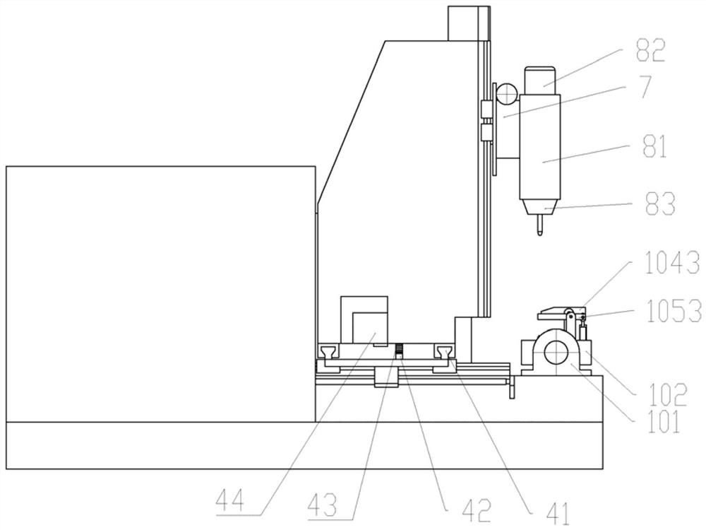
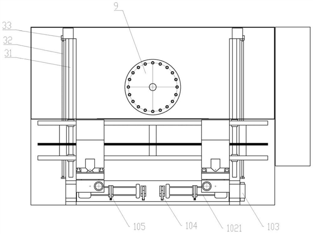
[0022] Such as Figure 1-4 As shown, the full-process automatic machining system for the front axle of this embodiment includes a base 1 and a control center 2, the base 1 is provided with a longitudinal guide device 3, and the longitudinal guide device 3 is slidably connected to a transverse guide device 4 , the horizontal guiding device 4 is slidably connected with two booms 5, the front side of the boom 5 is provided with a vertical guiding device 6, and the vertical guiding device 6 is slidingly connected with a flange 7, and the flange 7 is provided with a spindle box 8; the position behind the middle of the base 1 is provided with a tool magazine 9, the tool magazine 9 is located below the transverse guide device 4, and the front position of the base 1...


PUM


Abstract

The invention relates to the technical field of machining centers, and particularly relates to a full-process automatic machining system for a front shaft. The full-process automatic machining systemcomprises a base and a control center, wherein the base is provided with a longitudinal guide device; the longitudinal guide device is connected with a transverse guide device in a sliding manner; thetransverse guide device is connected with two arm frames in a sliding manner; the arm frames are provided with vertical guide devices; the vertical guide devices are connected with flange plates in asliding manner; the flange plates are provided with spindle boxes; a tool magazine is arranged at the position, close to the rear portion, of the middle of the base and positioned below the transverse guide device; a front shaft tool is arranged at the position, close to the front portion, of the base; and the longitudinal guide device, the transverse guide device, the vertical guide devices, theflange plates, the spindle boxes, the tool magazine and the front shaft tool are electrically connected with the control center. According to the full-process automatic machining system, the spindleboxes can complete longitudinal, transverse and vertical movement and can deflect overall, the deflection angle and cutting force of a tool are increased, and therefore the machining efficiency of a machine tool is improved.

Description

technical field [0001] The invention relates to the technical field of machining centers, in particular to a full-process automatic machining system for front axles. Background technique [0002] In mechanical processing, in order to improve product production efficiency and precision, CNC machine tools and machining centers are more and more used in production; the machining accuracy of the front axle is high, especially the main pins at both ends are set at oblique angles, and the front axle It is also long, so the tool deflection angle is required for drilling and face milling, and an orthogonal hole needs to be drilled at the root of the kingpin, and the front shaft needs to be rotated. Therefore, in order to meet the processing accuracy of the front shaft, the processing difficulty is reduced and the processing efficiency is improved. , The machining of the front axle is generally completed in the machining center. In the existing front-axis machining center, the tool ...

Claims


Application Information

Patent Timeline
Patent Type & Authority Applications(China)
IPC IPC(8): B23Q3/08B23Q3/00B23Q1/01B23Q3/155B23Q5/36B23Q5/40B23Q11/08
CPCB23Q1/017B23Q3/00B23Q3/082B23Q3/1552B23Q3/1554B23Q5/36B23Q5/40B23Q11/08
Inventor 石习勇金永洪任虎籍旭东周风琴
Owner HUBEI TRI RING AXLE
Why Eureka
Try Eureka