High deflection unrestrained pipe joint

a pipe joint, high deflection technology, applied in the direction of pipe joints, sleeve/socket joints, adjustable joints, etc., can solve the problems of high deflection pipe angles, high cost and bulk of typical joints required to achieve such unrestrained, ball and socket joints, etc., to achieve the effect of high deflection angl

Inactive Publication Date: 2016-11-24
MCWANE
View PDF7 Cites 4 Cited by
  • Summary
  • Abstract
  • Description
  • Claims
  • Application Information

AI Technical Summary

Benefits of technology

[0004]The present disclosure is directed to an improved pipe joining system including a first pipe having a bell or socket end and a second pipe having a male or spigot end, the pipes configured to form an unrestrained, push-fit, ring-seal assembly when operatively joined, the joined pipes capable of a high deflection angle.

Problems solved by technology

Telescopically assembled pipe joints that include tight seals, which also allow for high deflection (pivot) angles, however, remain a challenge for conventional pipe manufacturers.
The cost and bulk of a typical joint required to achieve such unrestrained, high deflection pipe angles remains burdensome or necessitates the use of a separate pipe fitting between the two pipes.
Ball and socket joints, for example, must be machined within close tolerances and are relatively expensive to produce.
Typical telescopically assembled joints require large bulky bells and sealing members to accommodate even moderate deflections.

Method used


Image

  • High deflection unrestrained pipe joint
  • High deflection unrestrained pipe joint
  • High deflection unrestrained pipe joint

Examples


Embodiment Construction

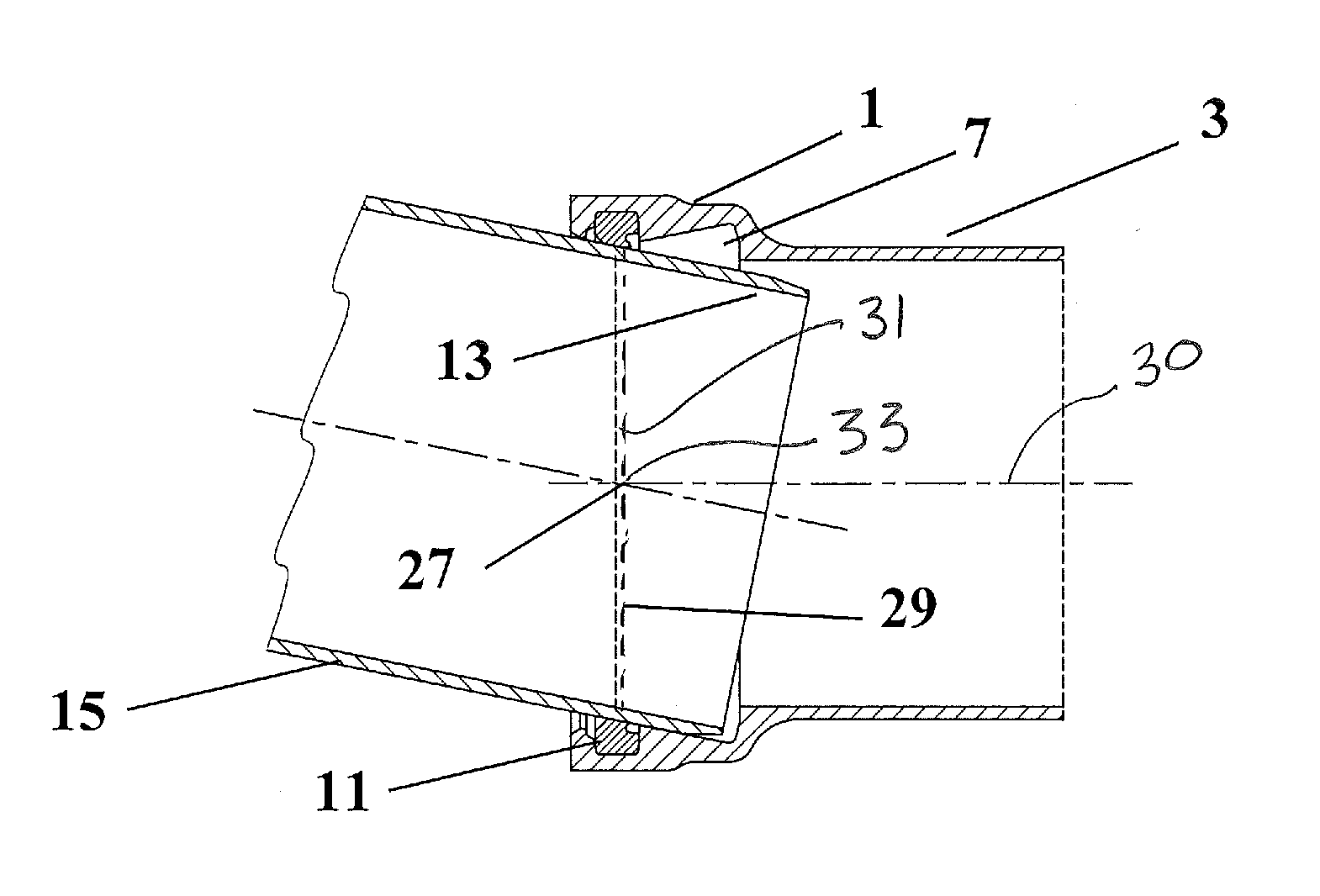
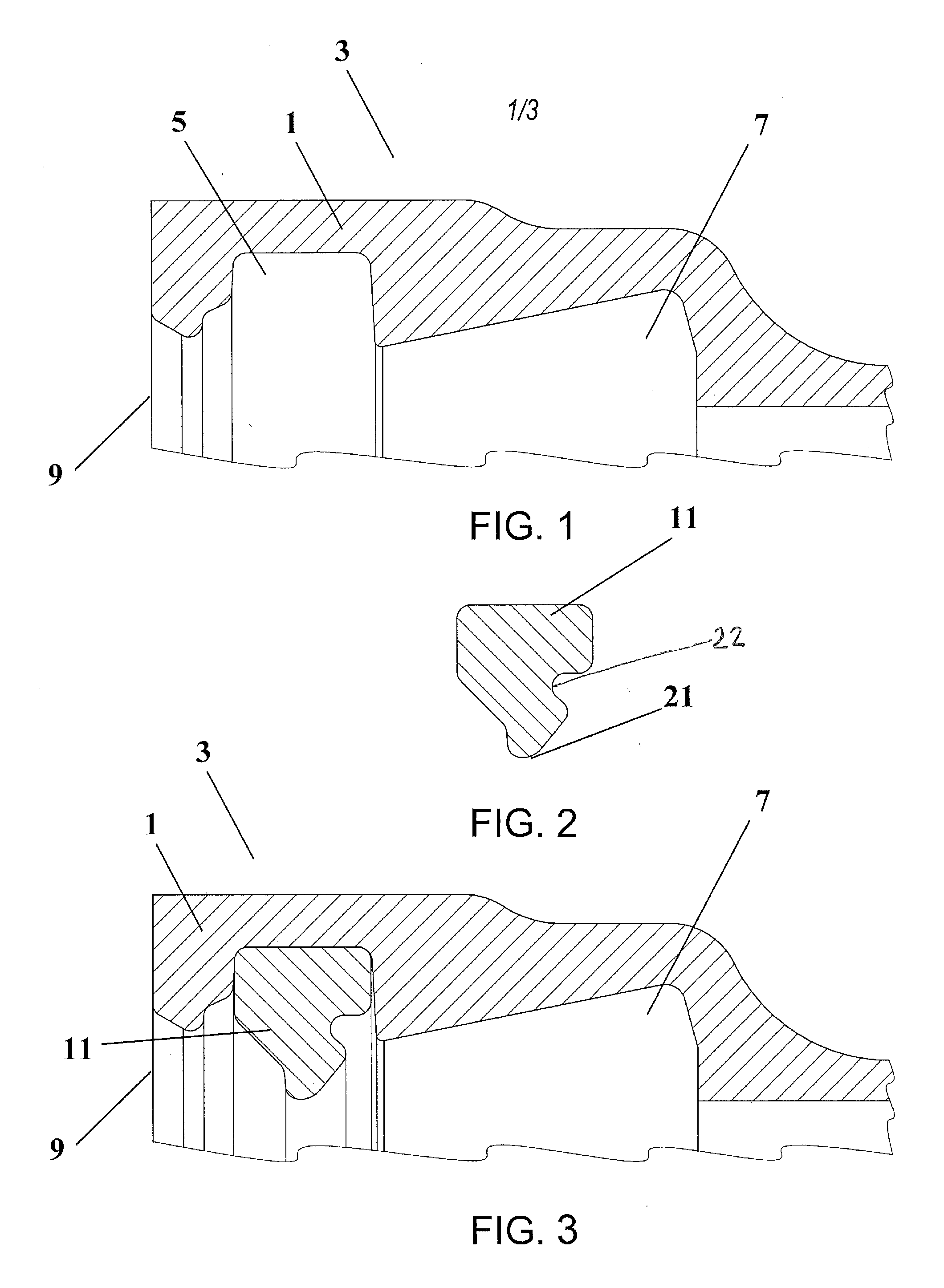
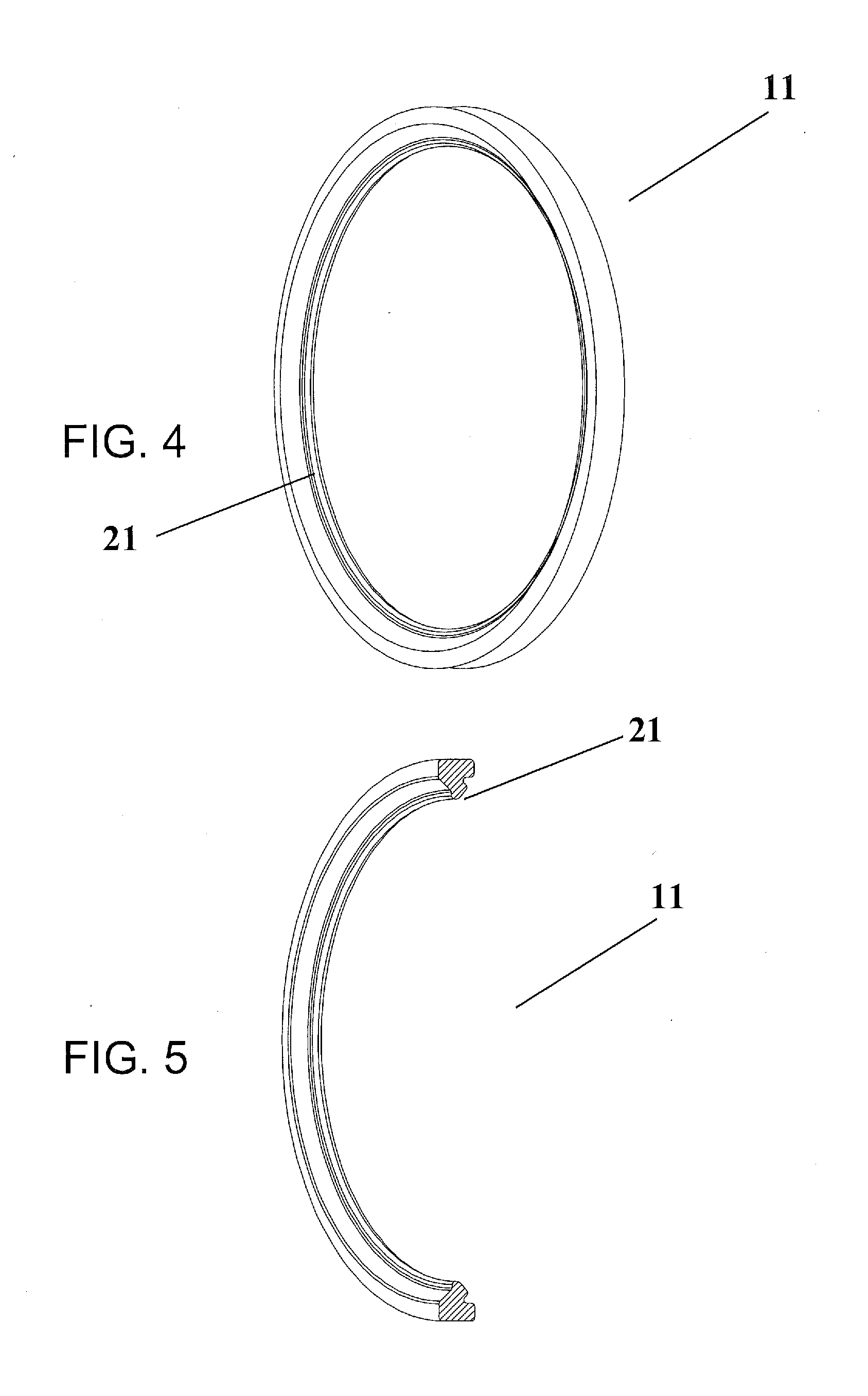
[0020]The present disclosure generally pertains to systems and methods for an improved pipe joint. The system includes a first pipe having a bell socket end and a second pipe having a male or spigot end. The bell socket end of the first pipe is configured to include an inner groove within which a sealing member may be inserted. The bell socket end of the first pipe further includes a pivot cavity. The spigot end of the second pipe may be inserted into bell socket end of the first pipe to form a pivotable, unrestrained, push-fit, ring-seal assembly when operatively joined. The circumferential sealing area formed by the sealing member's interaction with the spigot of the second pipe defines a sealing plane that is longitudinally located in relatively close proximity with a pivot plane of the two pipes, thereby allowing a high deflection angle with a relatively low bell and sealing member mass.

[0021]The use of any and all examples, or exemplary language (“e.g.,”“such as,” or the like) ...


PUM


Abstract

The present disclosure generally pertains to systems and methods for an improved pipe joint. The system includes a first pipe having a bell socket end and a second pipe having a male or spigot end. The bell socket end of the first pipe is configured to include an inner groove within which a sealing member may be inserted. The bell socket end of the first pipe further includes a pivot cavity. The spigot end of the second pipe may be inserted into socket end of the first pipe to form an unrestrained, push-fit, ring-seal assembly when operatively joined, such that a sealing member is located within the inner groove, the sealing member having a sealing surface that is longitudinally related with the pivot point of the two pipes thereby allowing a high joint deflection angle while maintaining a relatively small pipe bell and sealing member mass.

Description

FIELD OF INVENTION[0001]The present invention relates generally to an unrestrained pipe joint, and more particularly, to a pipe joint including a spigot end of a second pipe that is angularly deflectable within a bell socket end of a first pipe about a pivot point that has a specified positional relationship with an annular seal of the bell socket end.BACKGROUND OF THE INVENTION[0002]Telescopically assembled pipes are used in numerous applications. In short, the spigot end of one pipe is inserted into the socket end of a second pipe. The opening of the socket end of tone pipe is configured to receive the spigot end of another pipe, which becomes partially enclosed by the first pipe. A sealing member, such as a gasket may be inserted in the socket end to enhance the seal between the two pipes.[0003]Telescopically assembled pipe joints that include tight seals, which also allow for high deflection (pivot) angles, however, remain a challenge for conventional pipe manufacturers. The cos...

Claims


Application Information

Patent Timeline
Patent Type & Authority Applications(United States)
IPC IPC(8): F16L27/02
CPCF16L27/02F16L27/1021F16L21/03F16L27/1017
Inventor COPELAND, DANIEL A.
Owner MCWANE
Why Eureka
Try Eureka