Load and system

a load and system technology, applied in the field of load and system, can solve the problems of complicated and expensive, difficult installation of t-pieces, and achieve the effect of simple and cost-effective wiring

Active Publication Date: 2007-06-28
SEW-EURODRIVE GMBH & CO KG
View PDF5 Cites 12 Cited by
  • Summary
  • Abstract
  • Description
  • Claims
  • Application Information

AI Technical Summary

Benefits of technology

[0003] Example embodiments of the present invention may provide simpler and more cost-effective wiring in electrical loads and systems.

Problems solved by technology

These T-pieces are difficult to install and expensive, in particular when they must be usable and provide a high degree of protection in wet areas or even aseptic areas.
Therefore, they are complicated and expensive, especially with regard to installation as well.

Method used


Image

  • Load and system
  • Load and system
  • Load and system

Examples


Embodiment Construction

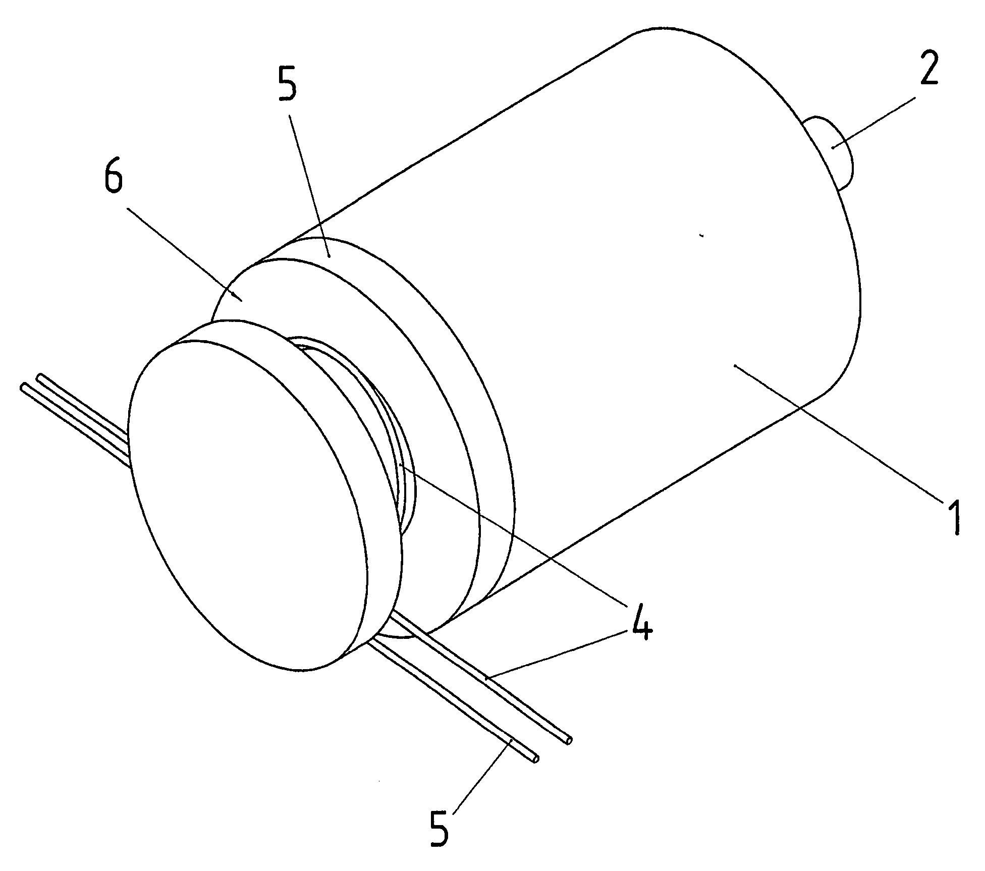
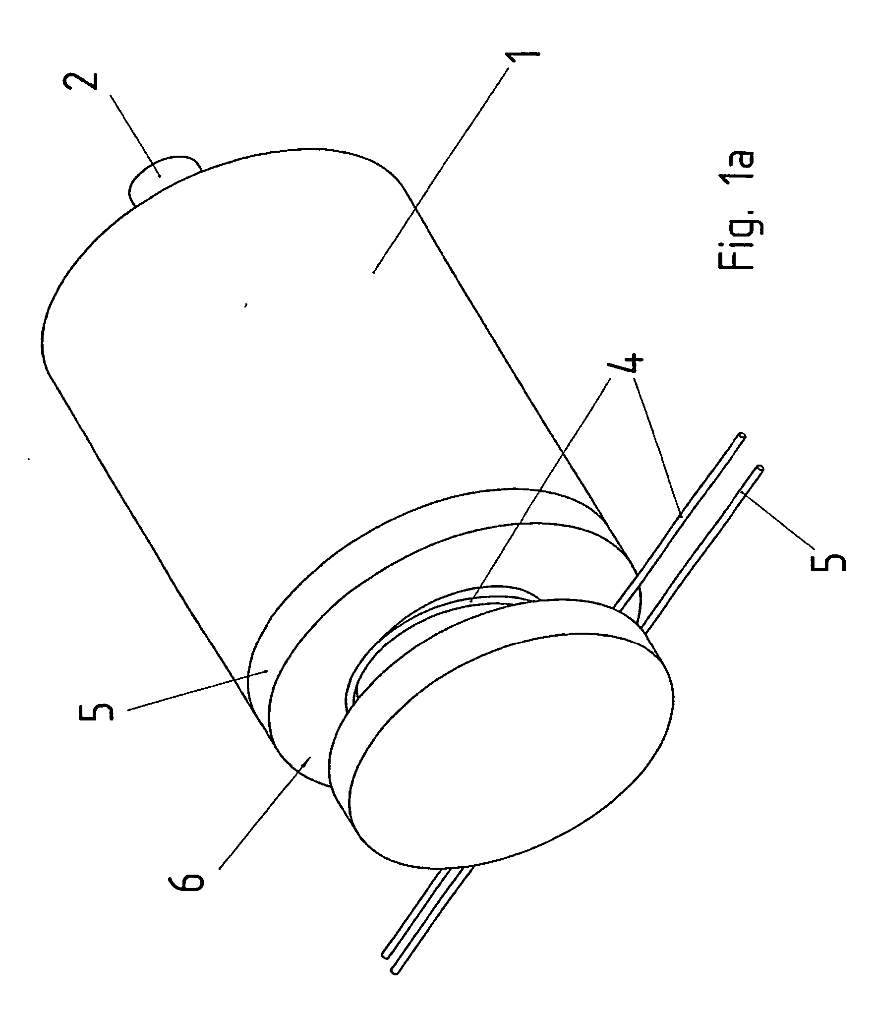
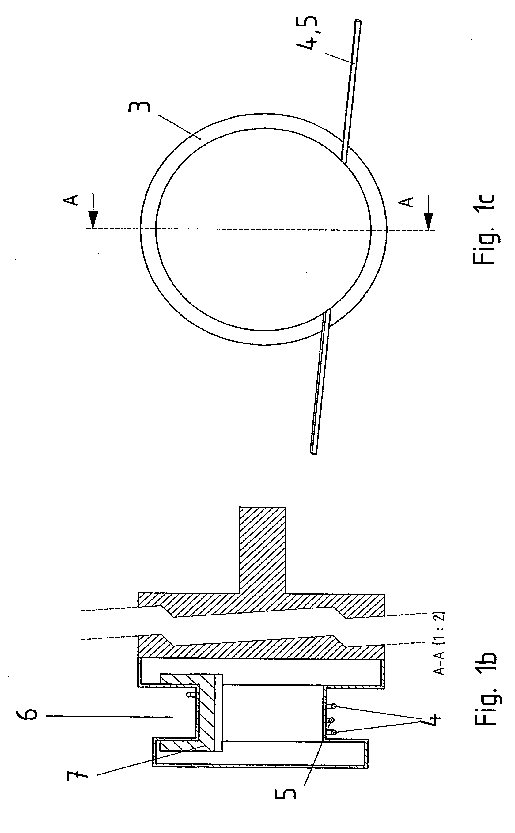
[0042] Illustrated in FIGS. 1a, 1b, and 1c are an isometric view, a sectional view, and a top view of a drive unit in the form of a load according to an example embodiment of the present invention. The drive unit includes an electric motor having a rotor shaft 2, which is surrounded by a housing 1. The electronic circuit for powering and controlling the electric motor is substantially protected by housing part 3, which has an indentation 6 in which a primary conductor is secured, using a winding loop. The return line, i.e., the second primary conductor, is only lead through, i.e., not wrapped around the drive unit.

[0043] Housing part 3 includes a core 7 having a U-shaped cross-section, into which a secondary winding is arranged that powers the electronic circuit. Therefore, the load may be powered by the inductive coupling in a contactless manner, and is therefore galvanically separated from the primary circuit. The power supply of the load may be disconnected rapidly and easily by...


PUM


Abstract

A load, including an electric motor and electronic circuit for powering the electric motor, the load being inductively powered.

Description

FIELD OF THE INVENTION [0001] The present invention relates to a load and a system. BACKGROUND INFORMATION [0002] In industrial plants, it is conventional that electrical loads, such as electronic devices, lighting devices, drives, machines, and the like can be powered from a network, in particular using alternating current at 50 or 60 Hz. To this end, the loads are mostly mechanically attached and electrically connected by expensive plug-and-socket connectors. In addition, most of such systems or machines have a T-piece for each drive unit as an energy branch. These T-pieces are difficult to install and expensive, in particular when they must be usable and provide a high degree of protection in wet areas or even aseptic areas. These T-pieces are also referred to as distribution boxes and often include additional device parts as well, such as emergency-off switches. Therefore, they are complicated and expensive, especially with regard to installation as well. SUMMARY [0003] Example ...

Claims


Application Information

Patent Timeline
Patent Type & Authority Applications(United States)
IPC IPC(8): G05B11/12H02J17/00
CPCH02J5/005H02J50/12
Inventor SIMON, OLAFMAHLEIN, JOCHENSCHMIDT, JOSEF
Owner SEW-EURODRIVE GMBH & CO KG
Why Eureka
Try Eureka