Image blurring correction apparatus
- Summary
- Abstract
- Description
- Claims
- Application Information
AI Technical Summary
Benefits of technology
Problems solved by technology
Method used
Image

Examples
Embodiment Construction
[0033] Hereafter, preferred embodiments of an image blurring correction apparatus according to the present invention will be described in detail by referring to the attached drawings.
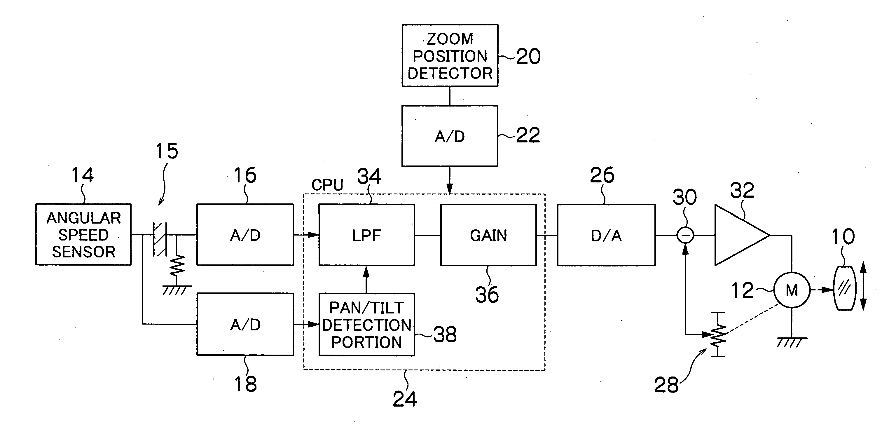
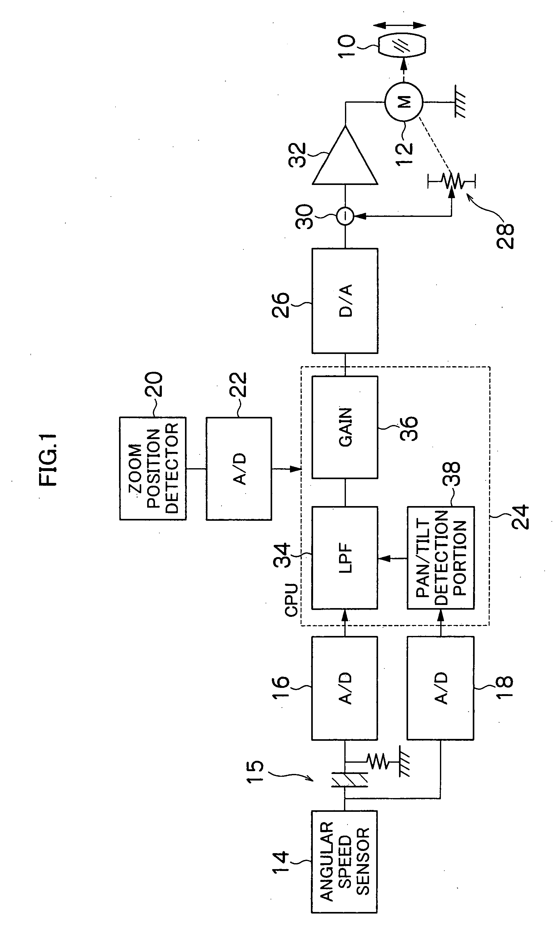
[0034]FIG. 1 is a block diagram showing the embodiment of the image blurring correction apparatus according to the present invention. The image blurring correction apparatus is mounted on a lens apparatus (taking lens) for a TV camera, a movie camera or a still camera and so on for instance. A vibration-proof lens 10 shown in FIG. 1 is placed to be movable up and down (vertical direction) and right and left (horizontal direction) within a surface perpendicular to an optical axis in the lens apparatus or an image taking optical system of the camera on which this apparatus is mounted. The vibration-proof lens 10 is driven vertically or horizontally by a motor 12, and if the camera (image taking optical system) is vibrated, it is moved by the motor 12 to a position for preventing an image blurring (positi...
PUM
 Abstract
Description
Claims
Application Information