Surface light source device and display device using the same
a technology of surface light source and display device, which is applied in the field of light source, can solve the problems of insufficient display quality, insufficient light diffusion, and generation of luminous unevenness, and achieve the effects of high efficiency of light use, sufficient display quality, and high evenness of in-plane luminan
- Summary
- Abstract
- Description
- Claims
- Application Information
AI Technical Summary
Benefits of technology
Problems solved by technology
Method used
Image
Examples
embodiment 1
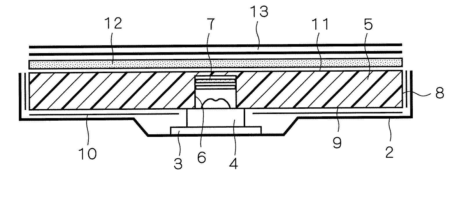
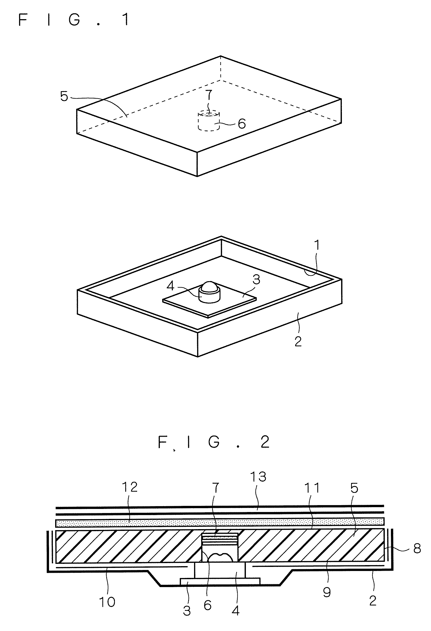
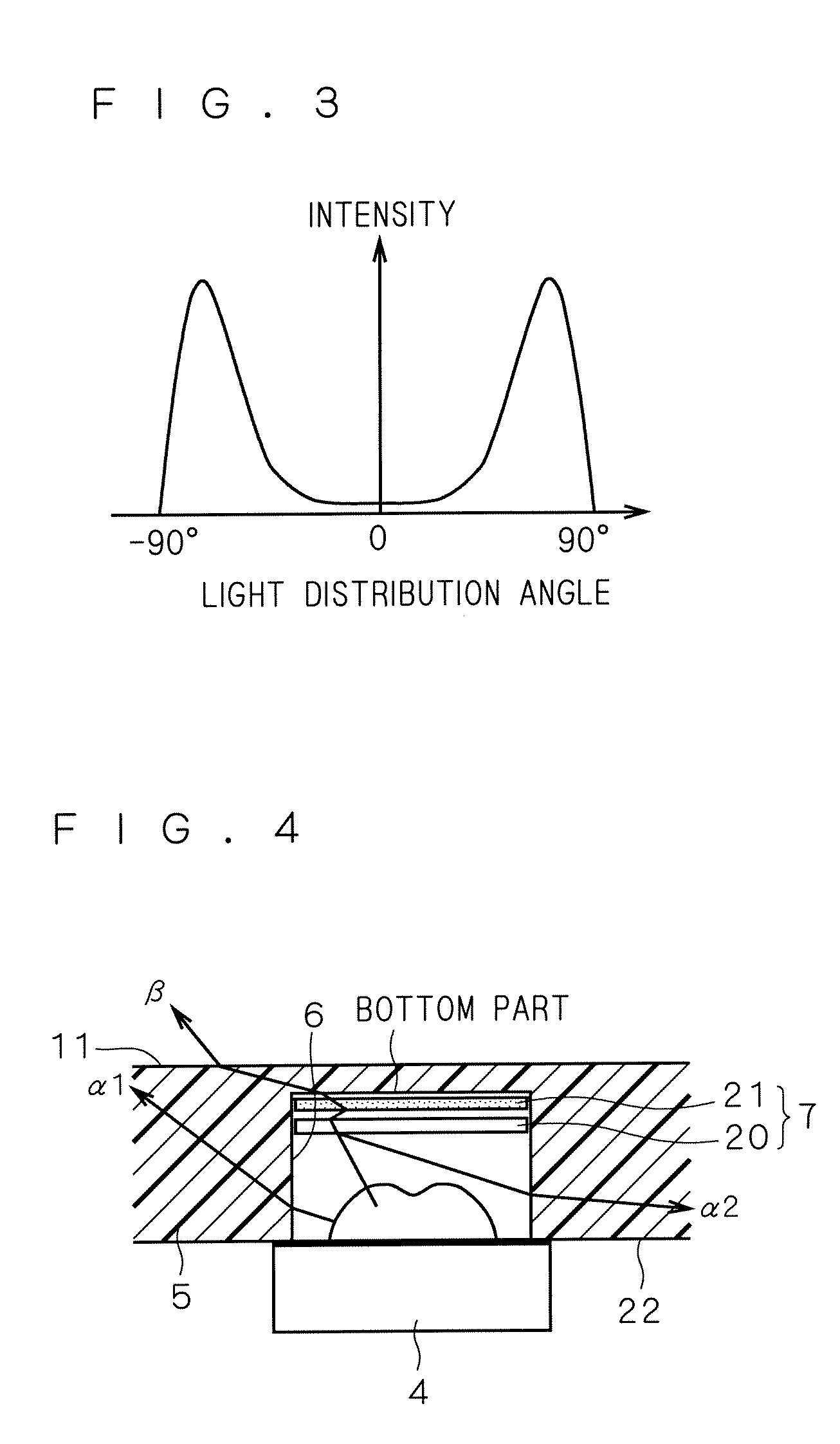
[0026]FIG. 1 is an exploded perspective view of a surface light source device according to the present embodiment. FIG. 2 is a sectional view of the surface light source device according to the present embodiment. The surface light source device shown in FIG. 1 has a housing 2 having an opening 1 formed at its one face, an LED (Light Emitting Diode) light source 4 held at the face opposite to the opening 1 through an LED substrate 3, a light guiding plate 5 disposed at the position for covering the opening 1 and the LED light source 4, a cylindrical recess 6 formed at the position of the light guiding plate 5 corresponding to the LED light source 4, and light quantity adjusting means 7 provided at the bottom part of the recess 6. As apparent from FIG. 2, a part of the LED light source 4 is housed in the recess 6.
[0027] A reflection sheet 10 is provided between the light guiding plate 5 and the housing 2 (at the side face 8 and the reflection and emission face 9 of the light guiding...
embodiment 2
[0067]FIG. 8 is a sectional view showing a surface light source device according to the present embodiment. In the surface light source device shown in FIG. 8, the light guiding plate 5 is provided at the position corresponding to the LED light source 4 and has a cylindrical recess 6 that stores a part of the LED light source 4 and a cylindrical recess 30 formed on the surface thereof opposite to the surface having the recess 6 formed thereon, wherein the light quantity adjusting means 7 for adjusting light from the LED light source 4 is further provided at the bottom part of the recess 30. Specifically, the light guiding plate 5 shown in FIG. 8 has the recess 6 at the side of the reflection and emission surface 9 and the recess 30 at the side of the emission surface 11 so as to be disposed back-to-back. Further, the light quantity adjusting means 7 is provided at the bottom part of the recess 6 at the side of the reflection and emission surface 9 in the embodiment 1, but in the pre...
embodiment 3
[0075]FIG. 9 is a schematic view of the reflection sheet 20 used for the light quantity adjusting means 7 according to the present embodiment. The reflection sheet 20 shown in FIG. 9 has a configuration in which a plurality of holes 40 are formed on the material of the reflection sheet 20 explained in the embodiment 1. The surface light source device in the present embodiment is the same as that shown in the embodiments 1 and 2 except that the reflection sheet 20 shown in FIG. 9 is used for the light quantity adjusting means 7. Therefore, the explanations for the components other than the reflection sheet 20 are omitted. The surface light source device in the present embodiment provides the operation and the effect same as those by the surface light source device in the embodiment 1 except for the operation and effect specific to the surface light source device in the present embodiment.
[0076] Usable materials for the reflection sheet 20 shown in FIG. 9 include a material obtained ...
PUM
 Abstract
Description
Claims
Application Information
 - R&D
- Intellectual Property
- Life Sciences
- Materials
- Tech Scout
- Unparalleled Data Quality
- Higher Quality Content
- 60% Fewer Hallucinations
Browse by: Latest US Patents, China's latest patents, Technical Efficacy Thesaurus, Application Domain, Technology Topic, Popular Technical Reports.
© 2025 PatSnap. All rights reserved.Legal|Privacy policy|Modern Slavery Act Transparency Statement|Sitemap|About US| Contact US: help@patsnap.com


