Surface light source device and display device using same

a surface light source and display device technology, applied in the direction of lighting and heating equipment, planar/plate-like light guides, instruments, etc., can solve the problems of deteriorating the display quality of the surface light source device, the non-uniformity of the luminance between the region of the point light source and the region near the adjacent point, etc., to achieve the effect of high display quality and minimal luminance non-uniformity

Active Publication Date: 2007-06-28
TRIVALE TECH
View PDF5 Cites 38 Cited by
  • Summary
  • Abstract
  • Description
  • Claims
  • Application Information

AI Technical Summary

Benefits of technology

[0008]It is an object of the present invention to provide a surface light source device capable of diminishing luminance non-uniformity between the region near a point light source and the region near between adjacent point light sources, as well as a display device of high display quality.
[0012]This surface light source device enables the uniformity of luminance distribution to be improved by having luminance continuously increase near the light incident surface of the light guide plate by disposing the light introducing means for forming an incident angle different from the incident angle of light directly entering into the side surface, on the side surface of the light guide plate located near between the point light sources adjacent to each other.

Problems solved by technology

When using the point light source, however, the light source is formed by arranging a plurality of light emitting diodes or the like in a row on the side surface of the light guide plate, and hence there may arise luminance non-uniformity between the region of the point light source, and the region near between the adjacent point light sources.
The luminance difference may deteriorate the display quality in this surface light source device.

Method used


Image

  • Surface light source device and display device using same
  • Surface light source device and display device using same
  • Surface light source device and display device using same

Examples


first preferred embodiment

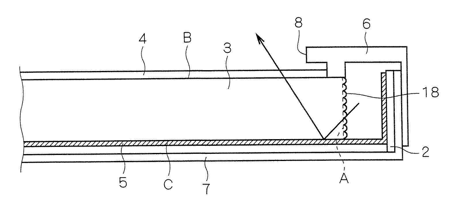
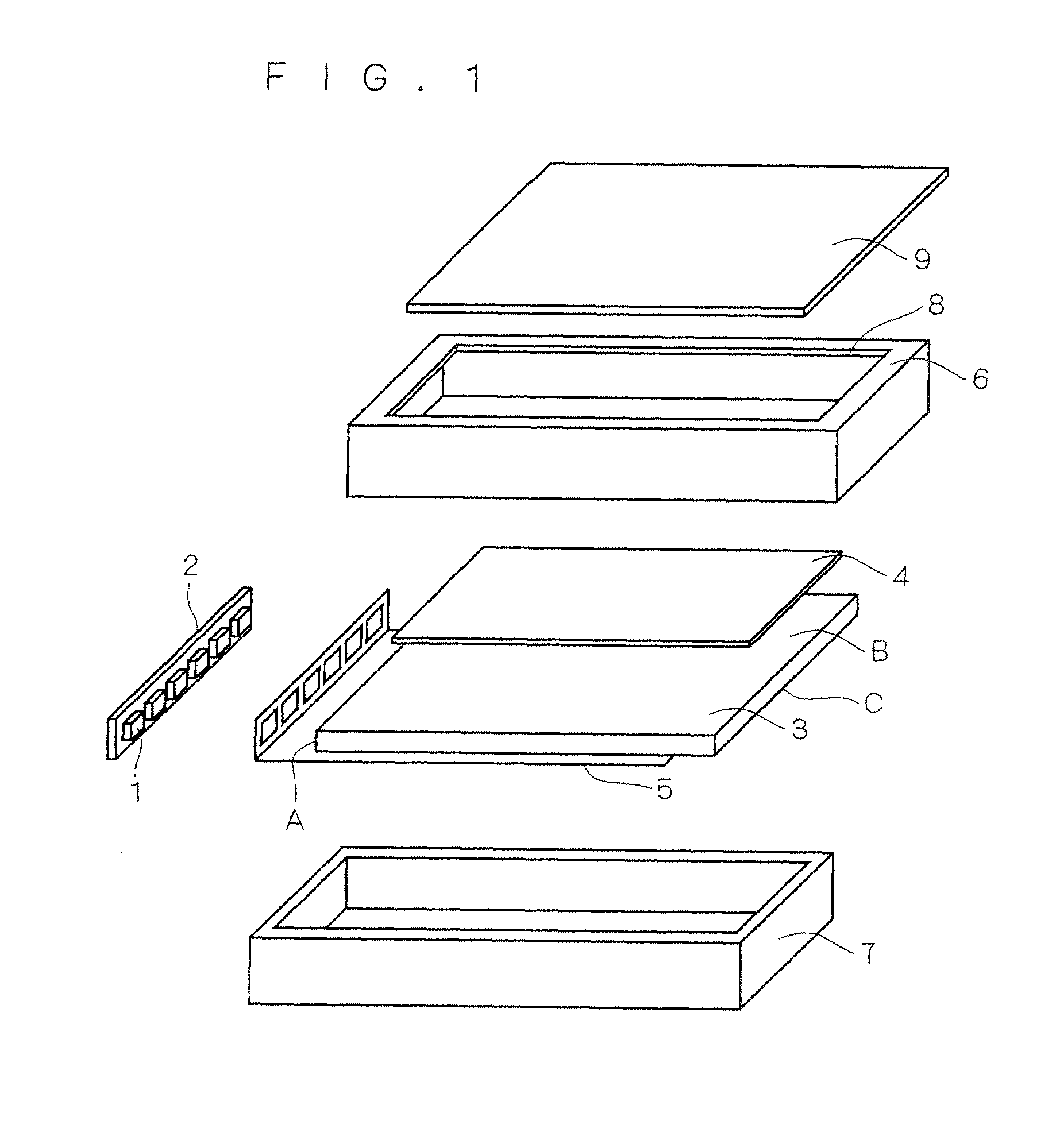
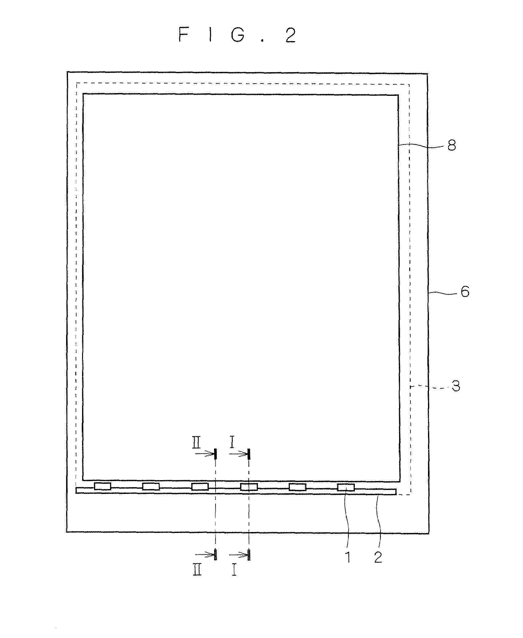
[0027]FIG. 1 is an exploded perspective view of a surface light source device according to a first preferred embodiment. FIG. 2 is a plan view of the surface light source device. In the surface light source device as shown in FIG. 1, a plurality of light emitting diodes (hereinafter referred to also as “LEDs”) 1 are arranged in a row and connected to an LED substrate 2. The LEDs 1 are arranged near one side surface located on a shorter side of a light guide plate 3 (hereinafter, a side surface into which the light emitted from a light source enters is referred to as a “light incident surface A”), and the light of the LEDs 1 entered from the light incident surface A is then emitted from a light emission surface B of the light guide plate 3.

[0028]Optical sheets 4 are disposed on the light emission surface B side of the light guide plate 3, and a reflecting sheet 5 is disposed on a light anti-emission surface C side of the light guide plate 3. The reflecting sheet 5 is also disposed on...

second preferred embodiment

[0063]FIG. 5 is a cross section in a region near between the adjacent LEDs 1 in a surface light source device according to a second preferred embodiment of the present invention. On the other hand, the construction in a region near the LEDs 1 of the surface light source device of the second preferred embodiment is basically the same as that of the first preferred embodiment. That is, the cross sectional construction in the region near the LEDs 1 is identical to that described with respect to FIG. 3, except for the absence of the space 11 and the second reflecting sheet 12. Therefore, the detailed descriptions of the construction and the optical path in the region near the LEDs 1 of the second preferred embodiment will be left out of the following.

[0064]The construction and the optical path in the region near between the adjacent LEDs 1 in the second preferred embodiment will next be described with reference to FIG. 5. Unlike the region near the LEDs 1, a convex portion 6a of an uppe...

third preferred embodiment

[0069]FIG. 6 is a cross section in a region near between adjacent LEDs 1 in a surface light source device according to a third preferred embodiment of the present invention. On the other hand, the construction in a region near the LEDs 1 of the surface light source device of the third preferred embodiment is basically the same as that of the first preferred embodiment. That is, the cross sectional construction in the region near the LEDs 1 is identical to that described with respect to FIG. 3, except for the absence of the space 11 and the second reflecting sheet 12. Therefore, the detailed descriptions of the construction and the optical path in the region near the LEDs 1 of the third preferred embodiment will be left out of the following.

[0070]The construction and the optical path near between the adjacent LEDs 1 in the third preferred embodiment will next be described with reference to FIG. 6. R-shaped portions 14 (portions shaped like a circular arc) are provided respectively at...


PUM


Abstract

The present invention provides a surface light source device capable of reducing luminance non-uniformity near point light sources and near between the point light sources adjacent to each other, and a display device of high display quality. The surface light source device includes: a plurality of LEDs arranged at a predetermined spacing; a light guide plate that emits, as a surface light, light emitted from the point light sources and entered into at least one side surface, through a light emission surface perpendicular to a light incident surface; reflecting sheets disposed respectively on a light anti-emission surface and near the LEDs in the light guide plate; and a casing having an opening part at a location corresponding to the light emission surface of the light guide plate, and holding the LEDs and the light guide plate and the reflecting sheets. The surface light source device further includes, near between the LEDs adjacent to each other, light introducing means for introducing the light emitted from the LEDs into the light emission surface or the light anti-emission surface.

Description

BACKGROUND OF THE INVENTION[0001]1. Field of the Invention[0002]The present invention relates to a surface light source device and a display device using the same, and more particularly, to a surface light source device using a point light source and a display device using the same.[0003]2. Description of the Background Art[0004]Liquid crystal display devices, signboards, guide lights and the like are not spontaneous emissive display devices whose display part itself emits light. It is required for these non-spontaneous emissive display devices to have a surface light source device such as a backlight on the back face of the display part.[0005]In a conventional surface light source device, a linear light source such as a cold cathode fluorescent tube, or a point light source such as a light emitting diode has been used as a light source disposed on a side surface of a light guide plate. When using the point light source, however, the light source is formed by arranging a plurality o...

Claims


Application Information

Patent Timeline
Patent Type & Authority Applications(United States)
IPC IPC(8): F21V7/04
CPCG02B6/0015G02B6/0055
Inventor SAKAI, SEIJIMORI, AKIHIRO
Owner TRIVALE TECH
Why Eureka
Try Eureka