
Electronic apparatus

a technology of electronic equipment and stopper, which is applied in the field of electronic equipment, can solve the problems of almost impossible or extremely difficult operation of the stopper member b>103/b>, and achieve the effect of small size and light weigh

Inactive Publication Date: 2007-06-28
SONY CORP
View PDF8 Cites 18 Cited by
  • Summary
  • Abstract
  • Description
  • Claims
  • Application Information

AI Technical Summary

Benefits of technology

The present invention relates to an electronic apparatus with a battery storing portion that can hold a battery unit without sliding it. The battery unit can be easily mounted and removed without moving it, which makes the electronic apparatus small and light. The technical effect of this invention is to provide a more convenient and easy-to-use electronic apparatus with a battery unit.

Problems solved by technology

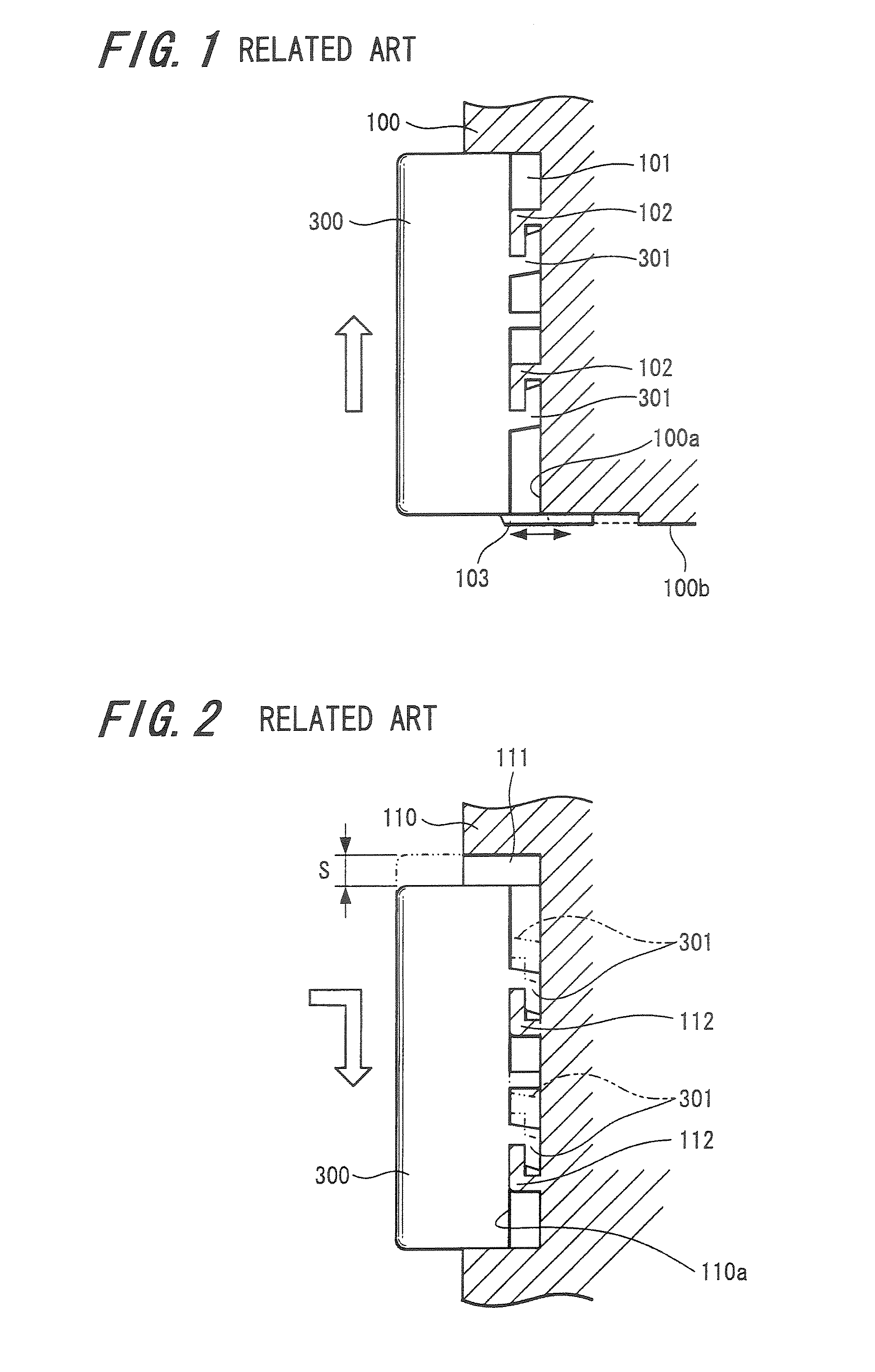
Further, the operation of sliding the stopper member 103 becomes almost impossible or extremely difficult in such a state that the electronic apparatus 100 is attached to the tripod.

Method used


Image

  • Electronic apparatus
  • Electronic apparatus
  • Electronic apparatus

Examples


embodiment 1

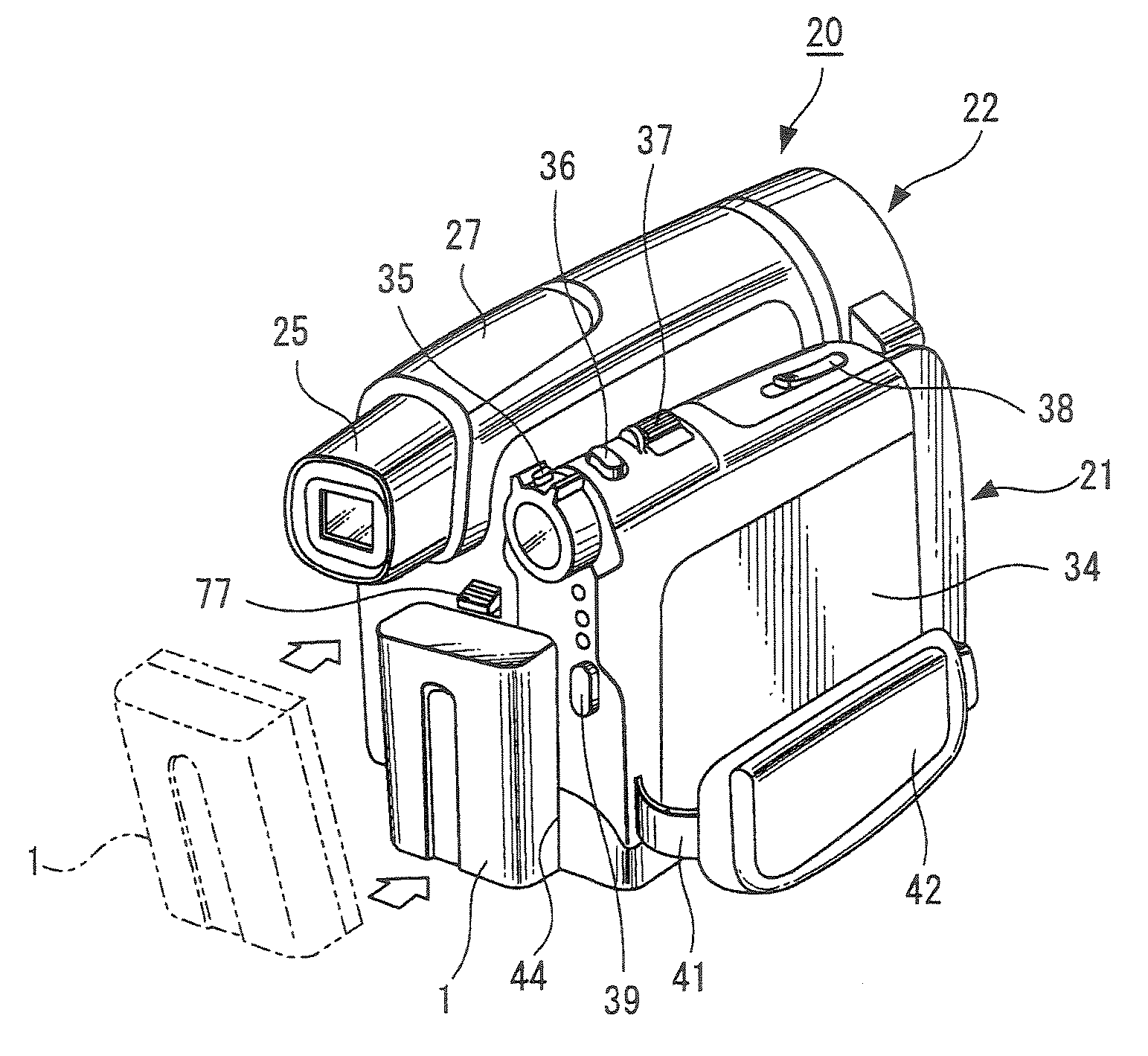
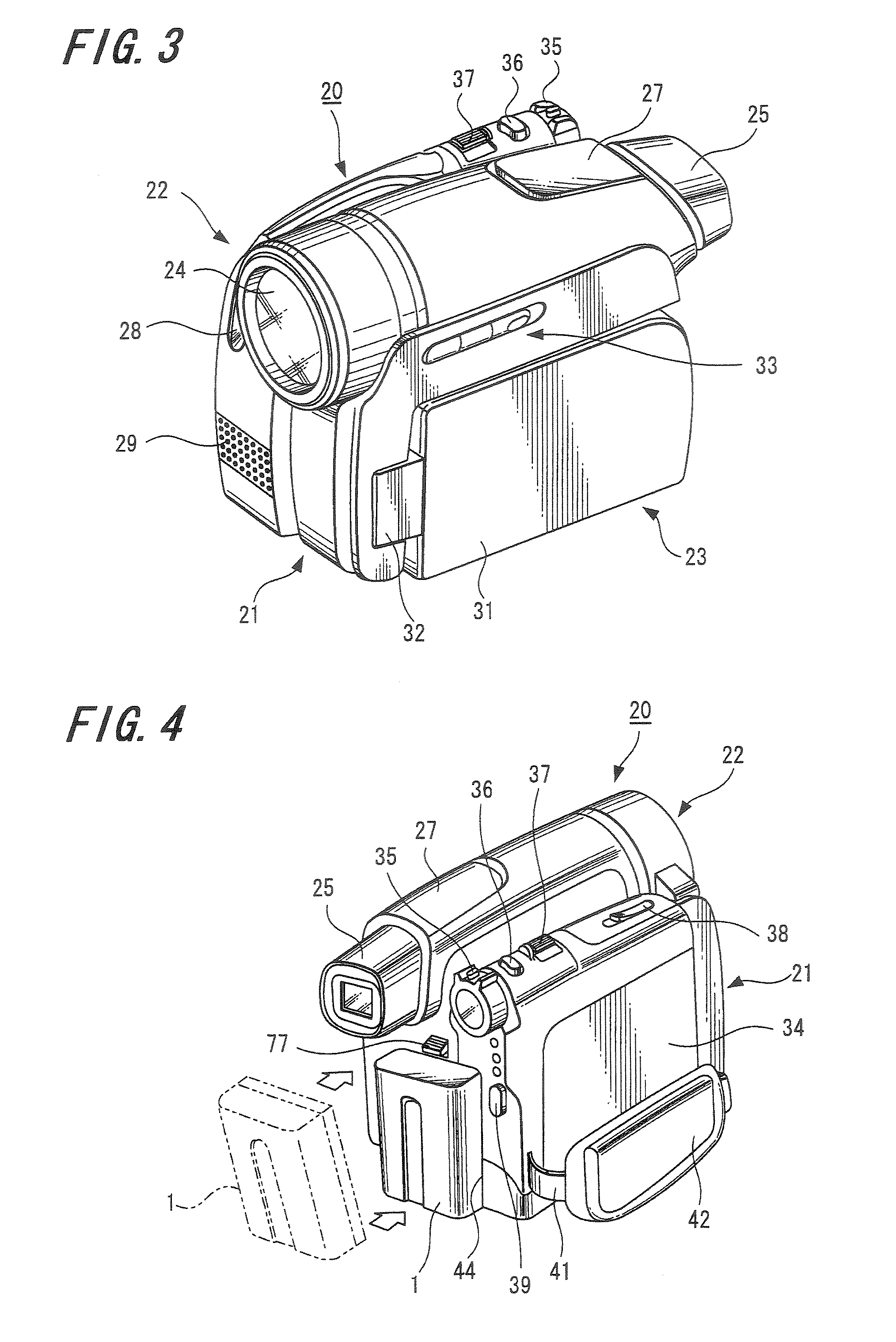
[0043]First, a first example of a battery unit suitably used for an imaging apparatus representing an electronic apparatus according to an embodiment of the present invention is explained with reference to FIGS. 21A and 21B, and FIGS. 22A through 22D. A battery unit 1 is configured to have a case 2, a rechargeable battery portion and control circuit substrate (not illustrated) provided inside the case 2, a battery-side connection terminal 3 provided in the case 2, and the like. The case 2 is constructed in the form of a block that is formed into an approximately rectangular parallelepiped unit in which L represents a size in the lengthwise direction; W represents a size in the width direction; and H represents a size in the height direction. The case 2 includes a body portion 4 in which one surface is open, and a base portion 5 that closes the opening portion of the body portion 4. Further, the connection terminal 3 is provided approximately in the center of a short side on one end ...


PUM

PropertyMeasurementUnit
widthaaaaaaaaaa
lengthaaaaaaaaaa
pressing forceaaaaaaaaaa

Abstract

An electronic apparatus includes: a case body having a battery storing portion formed of a concave portion whose shape is approximately corresponding to an external shape of a battery unit and a sliding member slidably supported on a surface of the case body on the opposite side to the battery storing portion. The battery storing portion has a width corresponding to that of the battery unit, a length corresponding to a length of the battery unit, and a body-side connection terminal connected to a connection terminal of the battery unit. The sliding member includes one or more engagement claws penetrating through the case body, projecting to the inside of the battery storing portion, capable of being engaged with engagement convex portions provided in the battery unit, and a biasing member causing the claws to be biased away from the body-side connection terminal and engaged with the engagement convex portions.

Description

CROSS REFERENCES TO RELATED APPLICATIONS[0001]The present invention contains subject matter related to Japanese Patent Application JP 2005-373037 filed in the Japanese Patent Office on Dec. 26, 2005, the entire contents of which being incorporated herein by reference.BACKGROUND OF THE INVENTION[0002]1. Field of the Invention[0003]The present invention relates to an electronic apparatus configured to have a battery unit representing a driving power source in a detachable manner.[0004]2. Description of the Related Art[0005]Japanese Unexamined Patent Application Publication No. 2005-190731 discloses an electronic apparatus of this kind in related art, for example. In this patent literature, there is described a battery lock mechanism of locking a battery and releasing the lock in a state where the battery representing a driving power source of an electronic apparatus is mounted on the electronic apparatus. The battery lock mechanism of the electronic apparatus described in Japanese Une...

Claims


Application Information

Patent Timeline
Patent Type & Authority Applications(United States)
IPC IPC(8): H01M2/10H01M50/202H01M50/244H01M50/296
CPCH01M2/1022H01M2/1055H01M2/1066Y02E60/10H01M50/213H01M50/202H01M50/296H01M50/244H01M50/10H01M50/20H01M50/00
Inventor NAGAI, MASANORIINABA, SHIGEKAZUTSUMURA, TOMOHIROAMATATSU, SEIYA
Owner SONY CORP
Learn More