Electromagnetic encoder

a technology of electromagnetic encoder and encoder body, which is applied in the direction of coils, instruments, measurement devices, etc., can solve the problems of difficult to obtain strong signals and attenuation of generated induction current, and achieve the effect of reducing scale width, reducing scale width and increasing the strength of receiving signals

Inactive Publication Date: 2011-10-20
MITUTOYO CORP
View PDF8 Cites 16 Cited by
  • Summary
  • Abstract
  • Description
  • Claims
  • Application Information

AI Technical Summary

Benefits of technology

[0017]According to the present invention, it is possible to downsize an encoder by reducing a scale width, that is, an encoder width. Also, since the entire length of the transmitting coils can be made smaller than that of Related Art 3, the receiving signal strength can be increased. Further, the total area of the encoder can be reduced, and thereby a small-sized encoder can be provided. Furthermore, it is possible to achieve an encoder that is strong with variation in a pitching direction by providing a plurality of receiving coils along a measuring direction.

Problems solved by technology

However, since the above-described configuration requires three lines of scale coils and makes wiring of the scale coils longer, generated induction current is attenuated by impedance of the scale coils themselves and it is difficult to obtain strong signals.

Method used


Image

  • Electromagnetic encoder
  • Electromagnetic encoder
  • Electromagnetic encoder

Examples


first embodiment

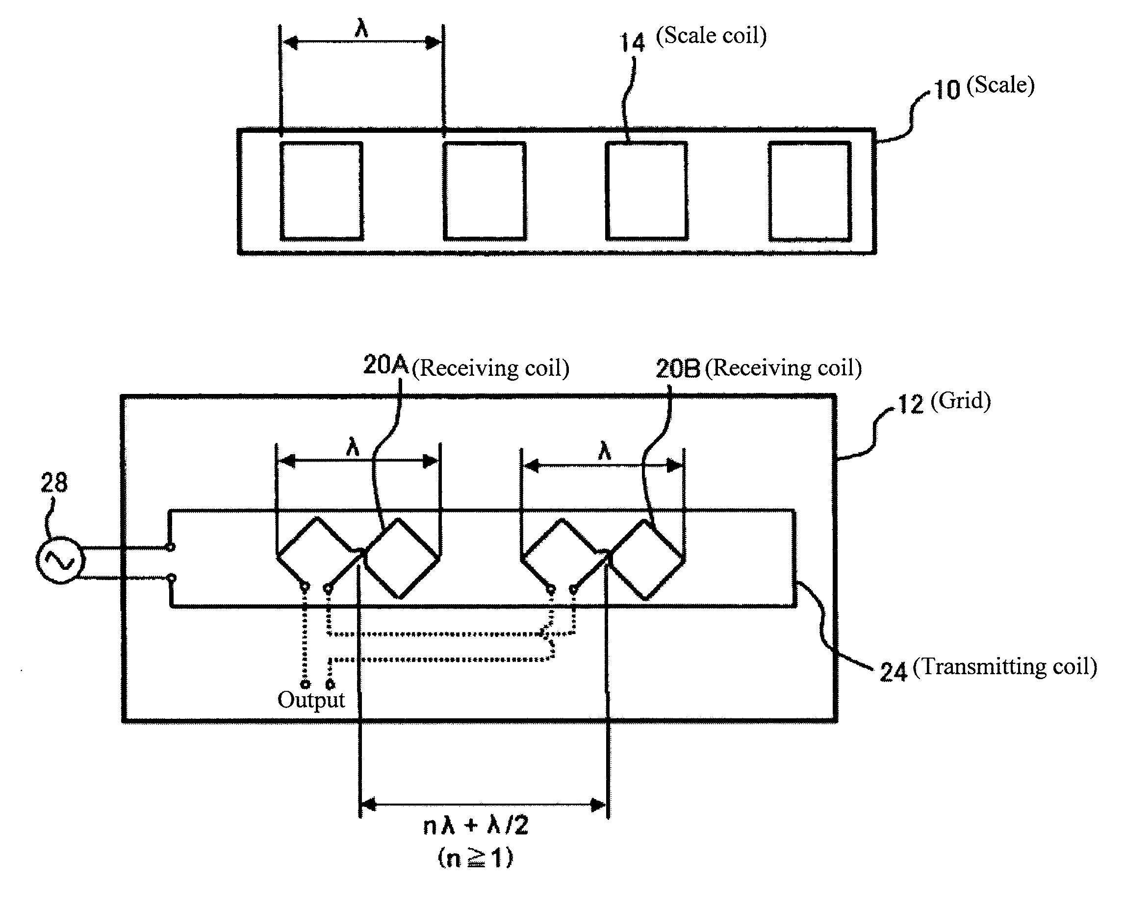
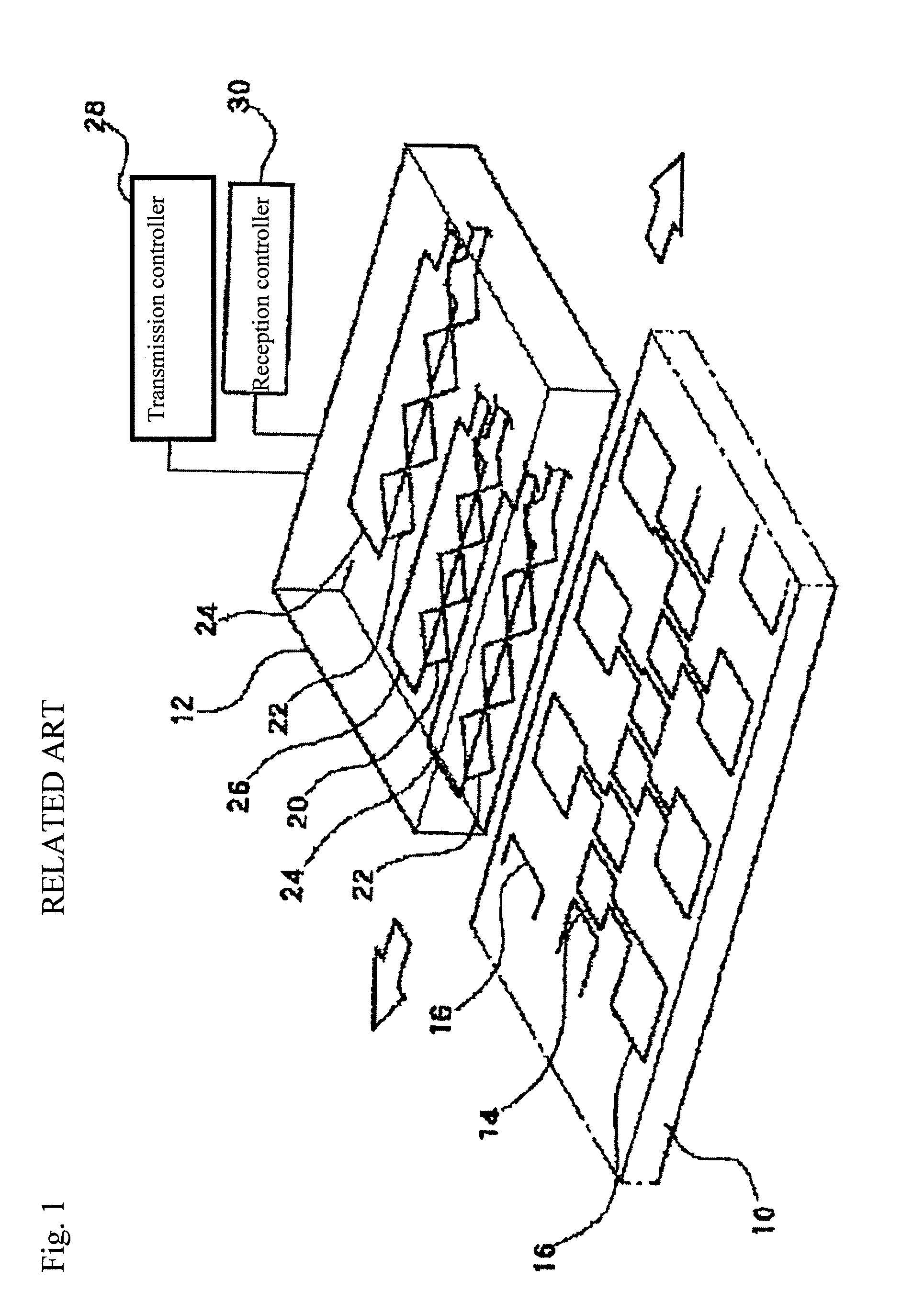
[0027]As shown in FIG. 4, a non-limiting feature of the present invention includes a plurality of scale coils 14 arranged on a scale 10 along a measuring direction; and a transmitting coil 24 and receiving coils arranged on a grid 12 to be movable relative to the scale 10 in the measuring direction, in which a relative movement amount between the scale 10 and the grid 12 is detected based on variation in magnetic flux detected by the receiving coils via the scale coils 14 at the time of exciting the transmitting coil 24. In the electromagnetic encoder, two sets of the receiving coils (20A, 20B) are provided along the measuring direction, and one of the receiving coils (for example, 20A) is displaced by a ½ phase of a scale pitch λ relative to the other of the receiving coils (for example, 20B).

[0028]The two sets of the receiving coils 20A and 20B have a common shape, and are connected so as to output difference between signals of the receiving coils 20A and 20B.

[0029]When electric c...

second embodiment

[0030]Next, a non-limiting feature of the present invention will be explained.

[0031]As shown in FIG. 6, the second embodiment makes it possible to measure the absolute position by providing two sets of tracks, each of which has the scale coils, the transmitting coil and the receiving coils according to the first embodiment, in a scale width direction with a different scale pitch λ1, λ2. One of the two sets of tracks has scale coils 14-1, a transmitting coil 24-1, and receiving coils 20-1A and 20-1B, and the other has scale coils 14-2, a transmitting coil 24-2, and receiving coils 20-2A and 20-2B.

[0032]According to the second embodiment, it is possible to achieve an encoder that can accurately measure an absolute position with a small scale width of two tracks.

[0033]The number of the track is not limited to two. Three or more tracks may be provided to increase the measuring area.

[0034]In the above-described embodiments, the shape of the receiving coil is rhomboid. However, the shape ...


PUM


Abstract

According to the present invention, an electromagnetic encoder includes a number of scale coils arranged on a scale along a measuring direction; and transmitting coils and receiving coils arranged on a grid to be movable relative to the scale in the measuring direction, in which a relative movement amount between the scale and the grid is detected based on variation in magnetic flux detected by the receiving coils via the scale coils at the time of exciting the transmitting coils, and the receiving coils are provided in the measuring direction to be a plurality of sets, one of the sets of the receiving coils being displaced by a ½ phase of a scale pitch relative to the other set of the receiving coils.

Description

CROSS-REFERENCE TO RELATED APPLICATIONS[0001]The present application claims priority under 35 U.S.C. §119 of Japanese Application No. 2010-096361, filed on Apr. 19, 2010, the disclosure of which is expressly incorporated by reference herein in its entirety.BACKGROUND OF THE INVENTION[0002]1. Field of the Invention[0003]The present invention relates to an electromagnetic encoder. Particularly, the present invention relates to a highly-accurate and low-cost electromagnetic encoder which is suitable for calipers, indicators, linear scales, micrometers, and the like, can achieve great signal strength by reducing offsets with a small scale width, that is, an encoder width, and is strong with variation in a pitching direction.[0004]2. Description of Related Art[0005]As disclosed in Related Art 1 and Related Art 2, and as FIG. 1 illustrates the example of Related Art 2, an electromagnetic encoder is known, which has a number of scale coils 14, 16 arranged on a scale 10 along a measuring di...

Claims


Application Information

Patent Timeline
Patent Type & Authority Applications(United States)
IPC IPC(8): G01B7/14
CPCG01D5/2086
Inventor SASAKI, KOUJI
Owner MITUTOYO CORP
Why Eureka
Try Eureka