Air valve, electronic blood pressure monitor, and air massager

Inactive Publication Date: 2006-07-13
OMRON HEALTHCARE CO LTD
View PDF8 Cites 16 Cited by
  • Summary
  • Abstract
  • Description
  • Claims
  • Application Information

AI Technical Summary

Benefits of technology

[0056] By these configurations, a coil or a moving iron core such as of a solenoid valve can be rendered unnecessary, thereby providing an air massager having a simple configuration. Further, driving sound from, for example, an electromagnetic valve can be eliminated, to reduce noise when the air valve is being driven. In addition, it is possible to operate the appar

Problems solved by technology

However, a structure of an air valve due to a conventional technology has a limit in miniaturization since coil or moving iron core is used.
Further, such a structure has large power dissipation and generates a magnetic field and so that possibly affect its peripheral components.
If the moving iron cor

Method used


Image

  • Air valve, electronic blood pressure monitor, and air massager
  • Air valve, electronic blood pressure monitor, and air massager
  • Air valve, electronic blood pressure monitor, and air massager

Examples


first embodiment

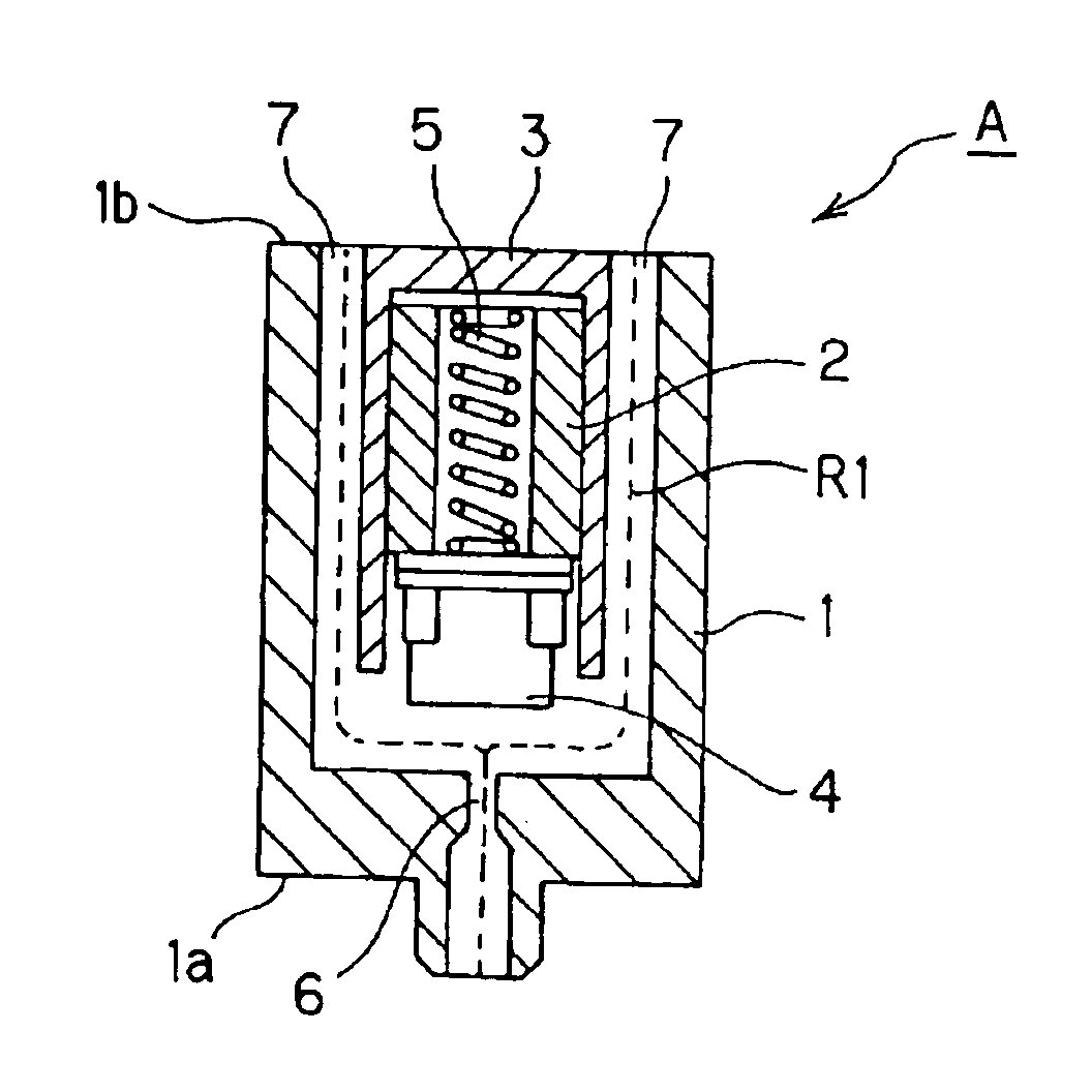
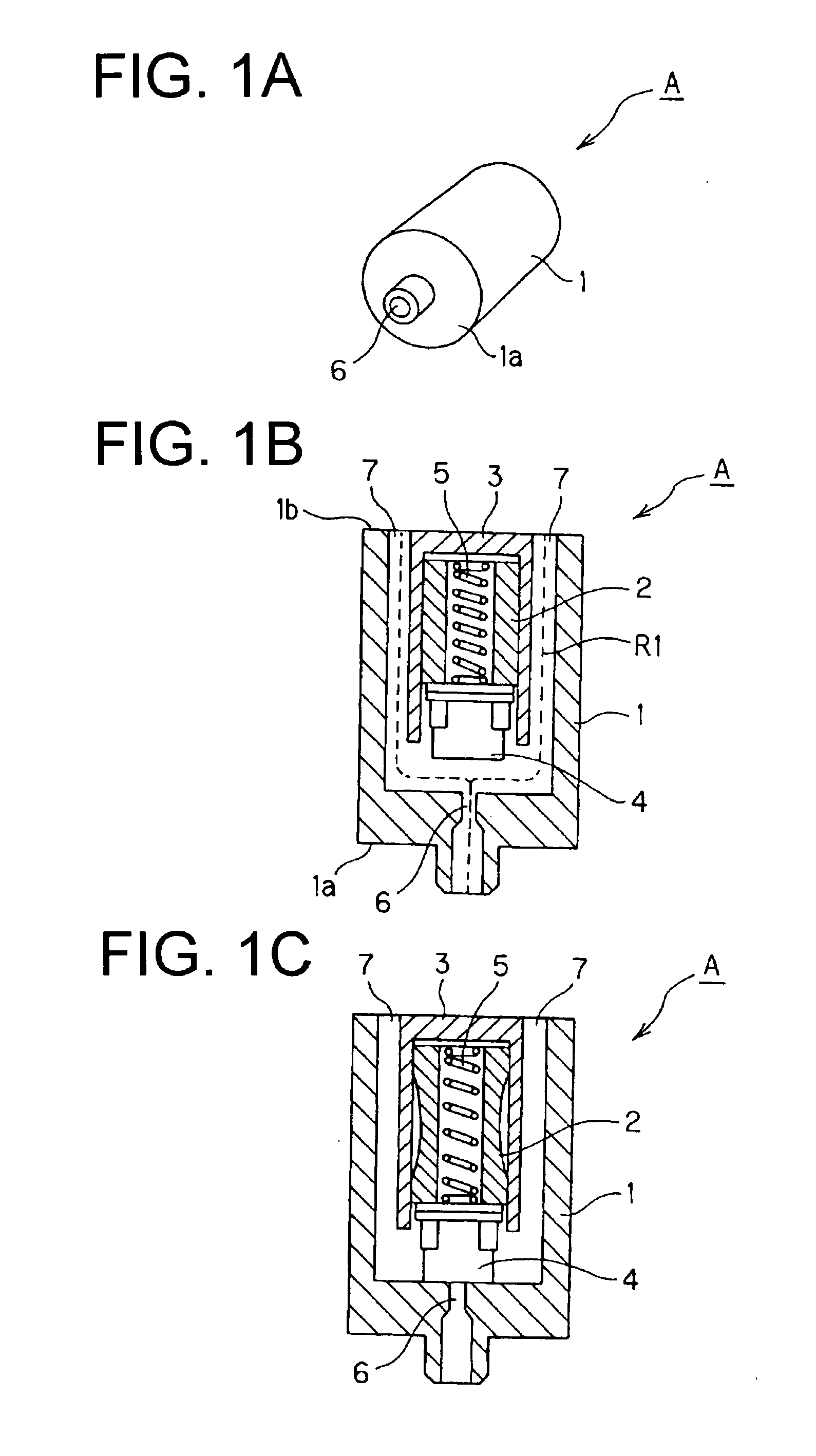
[0083] A configuration and a principle of an air valve related to the first embodiment are described with reference to FIG. 1. FIG. 1A is an external view of the air valve related to the first embodiment, FIG. 1B is a cross-sectional view of the air valve related to the first embodiment in a condition where its outflow route is opened, and FIG. 1C is a cross-sectional view of the air valve related to the first embodiment in a condition where its outflow route is closed.

[0084] The air valve A has a column-shaped housing member 1, a contractible / expandable actuator 2 provided in the housing member, a guide member 3 for guiding the actuator 2 so that it can be contracted and expanded in one direction, an elastic member 4 such as a packing provided to an end portion of the actuator 2 on its moving side, and a spring 5 provided as a flexible member in the cylinder-shaped actuator 2.

[0085] The guide member 3 protects the contractive / expansive section and guides its end portion on its mo...

second embodiment

[0098] A configuration and an operation of an air valve related to the second embodiment are described with reference to FIG. 5. FIG. 5A is a cross-sectional view of the air valve related to the second embodiment in a condition where its outflow route is opened and FIG. 5B is a cross-sectional view of the air valve related to the second embodiment in a condition where its outflow route is closed.

[0099] An air valve B has a column-shaped housing member 11, a contractible / expandable actuator 12 provided in the housing member, a guide member 13 for guiding the actuator 12 so that it can be contracted and expanded in one direction, an elastic member 14 such as a packing provided to an end portion of the actuator 12 on its moving side, and a spring 15 provided in the cylinder-shaped actuator 12.

[0100] One end face 11a of the housing member 11 has an inflow opening 16 formed therein for letting in gas from an airbag. Further, a side face of the housing member 11 has one or a plurality o...

third embodiment

[0108] A configuration and an operation of an air valve related to the third embodiment are described with reference to FIG. 6. FIG. 6A is a cross-sectional view of the air valve related to the third embodiment in a condition where its outflow route is opened and FIG. 6B is a cross-sectional view of the air valve related to the third embodiment in a condition where its outflow route is closed.

[0109] An air valve C has a column-shaped housing member 21, a contractible / expandable plate-shaped actuator 22 provided in the housing member, a guide portion 21b for holding an edge portion of the actuator 22 so that the actuator 22 may not be deviated, and an elastic member 24 such as a packing provided at a center of one surface of the actuator 22.

[0110] One end face 21a of the housing member 21 has an inflow opening 26 formed therein for letting in gas from an airbag. Further, a side face of the housing member 21 has a plurality of outflow openings 27 formed therein for discharging gas e...


PUM


Abstract

An air valve comprising: an inflow opening through which air flows in; an outflow opening through which the entered air flows out; and an actuator having an elastomer or polymer that can expand and contract when supplied with a voltage and an electrode for applying a voltage on the elastomer or polymer, wherein an outflow route from the inflow opening to the outflow opening is opened and closed by driving the actuator.

Description

BACKGROUND OF THE INVENTION [0001] 1. Field of the Invention [0002] The present invention relates to an air valve. More specifically, it relates to an electronic blood pressure monitor and an air massager that use the air valve. [0003] 2. Description of the Related Art [0004] Conventionally, a blood pressure of a man has been measured by winding an airbag (cuff) around his body (upper arm or wrist) and sending air into the airbag by using an air pump to obtain information of an arterial pulse wave that is sensed due to compression of the human body. Then, by depressurizing the airbag gradually to decompress the human body, measurement is finished. Therefore, to release the air in the airbag to an outside, a solenoid air valve has been utilized, the following configuration for which has been disclosed conventionally. [0005] Japanese Patent Application Laid Open Publication No. 9-135817 discloses a flow rate control valve for controlling a flow rate by pressing an outflow route with e...

Claims


Application Information

Patent Timeline
IPC IPC(8): A61B5/02
CPCA61B5/02141A61B5/0235A61H2201/0134A61H2201/0138A61H2201/0149A61M39/22F16K31/004F16K31/02A61B5/022A61H9/00
Inventor KISHIMOTO, HIROSHISANO, YOSHIHIKOKARO, HIROMICHI
Owner OMRON HEALTHCARE CO LTD
Why Eureka
Try Eureka