
Board layout structure of digital broadcast receiving portion

a technology of receiving portion and layout structure, applied in the direction of transmission, electrical equipment, etc., can solve the problems of troublesome digital broadcast receiving performance, difficult rendering of digital signal demodulation unit as a component, etc., and achieve the effect of preventing digital nois

Inactive Publication Date: 2007-06-28
ORION ELECTRIC CO LTD
View PDF9 Cites 0 Cited by
  • Summary
  • Abstract
  • Description
  • Claims
  • Application Information

AI Technical Summary

Benefits of technology

[0010] The present invention has been made in view of the problems, and provides a board layout structure of a digital broadcast receiving portion, wherein mutual positional relation between a digital signal demodulation unit and a digital tuner is interchangeable between right and left so as to suppress limitation on the layout of electronic components on a circuit board.
[0014] According to the configuration of the second aspect, the shield is rendered approximately U-shaped. It is thereby possible, on placing the digital signal demodulation unit at a position adjacent to the digital tuner, to securely prevent digital noise to the digital signal demodulation unit from the digital tuner whether the digital signal demodulation unit is placed on the right or on the left of the digital tuner.

Problems solved by technology

For this reason, the structure of one digital signal demodulation unit cannot be applied to an electronic device capable of receiving various digital broadcasts so that it has been difficult to render the digital signal demodulation unit as a component.
However, the pattern wiring for electrically connecting the digital IF signal output portion of the digital tuner to the IF input terminal of the digital signal demodulation unit becomes longer than the case of the board layout structure of FIG. 7 so that it may cause some trouble in digital broadcast receiving performance.

Method used


Image

  • Board layout structure of digital broadcast receiving portion
  • Board layout structure of digital broadcast receiving portion
  • Board layout structure of digital broadcast receiving portion

Examples


Embodiment Construction

[0024] Examples as preferred embodiments of the present invention will be described hereunder with reference to FIGS. 1 to 9. It goes without saying that the present invention is easily applicable to those other than what is described in the examples without departing from the scope of the invention.

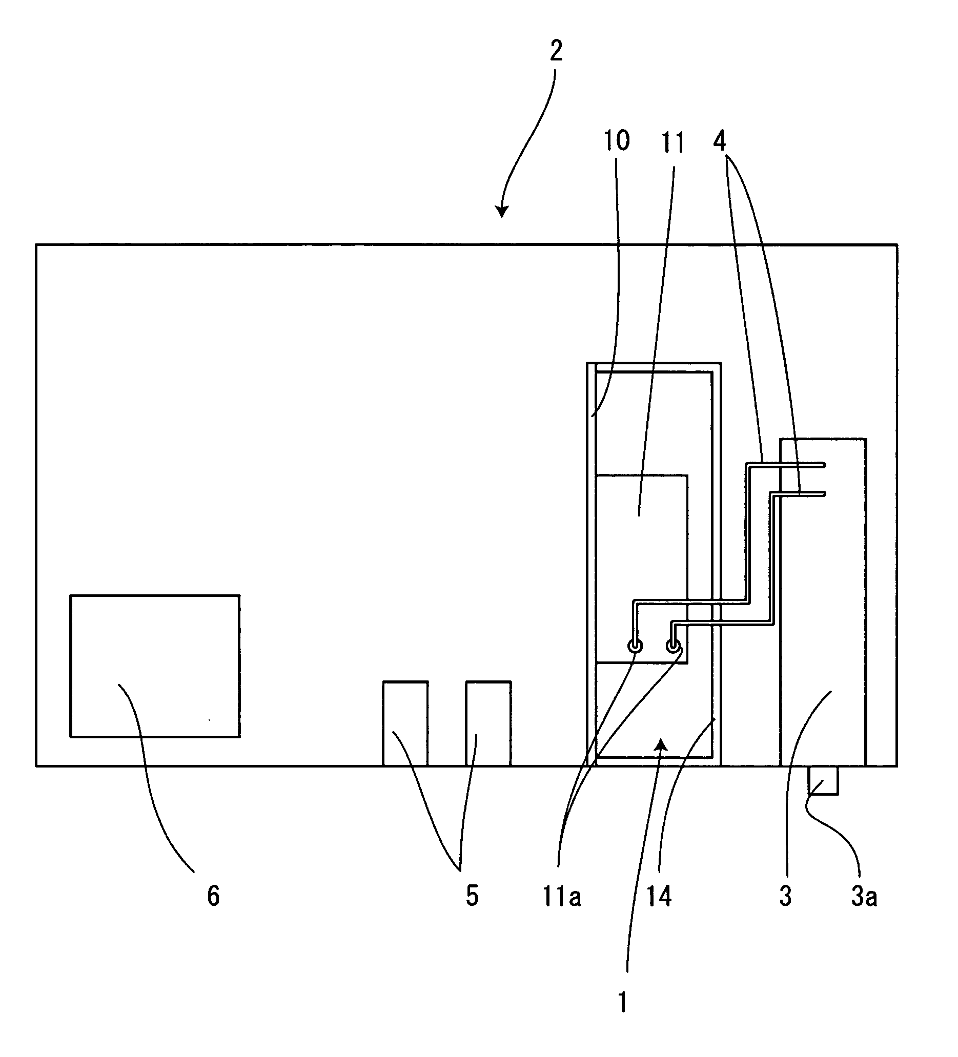
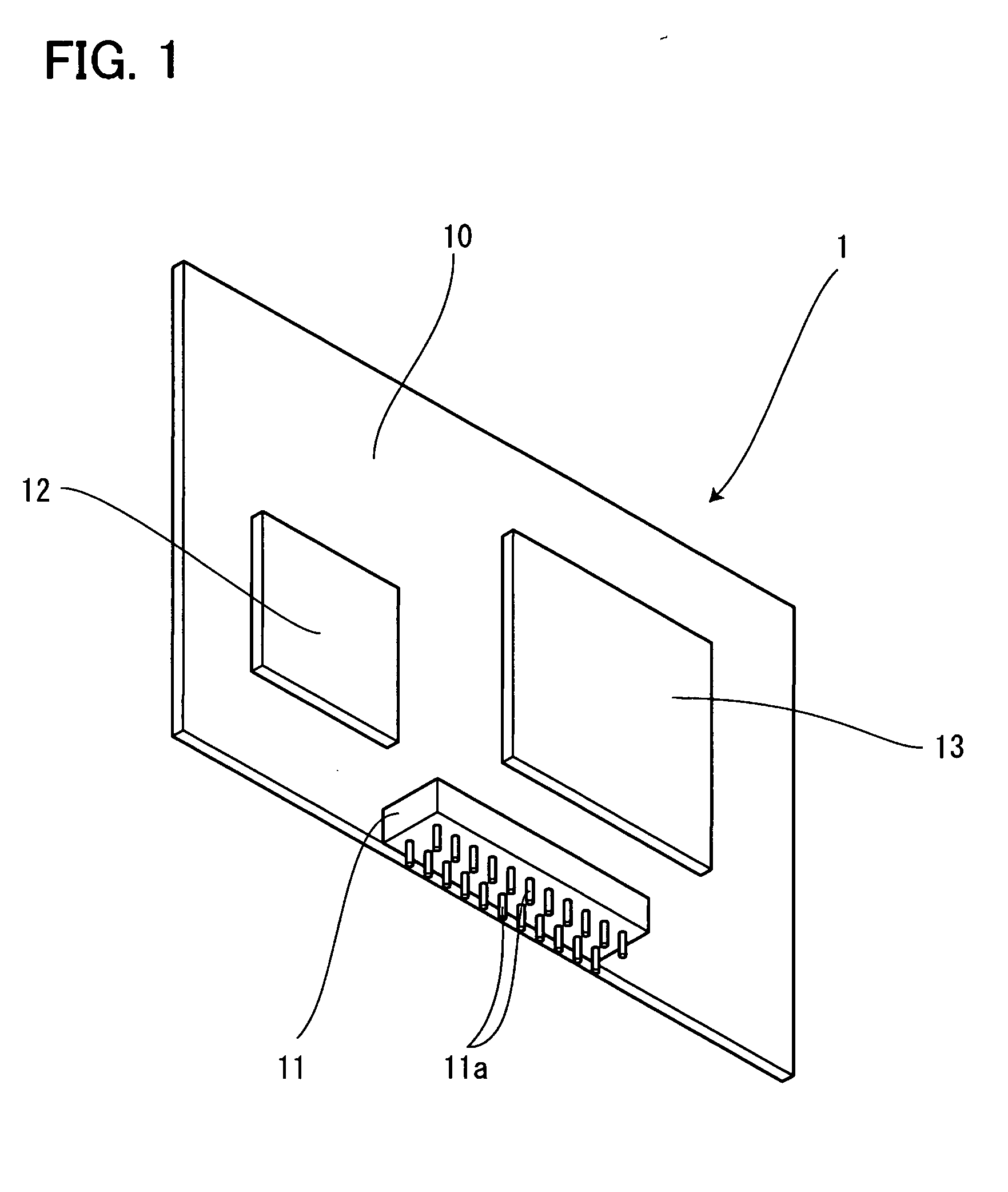
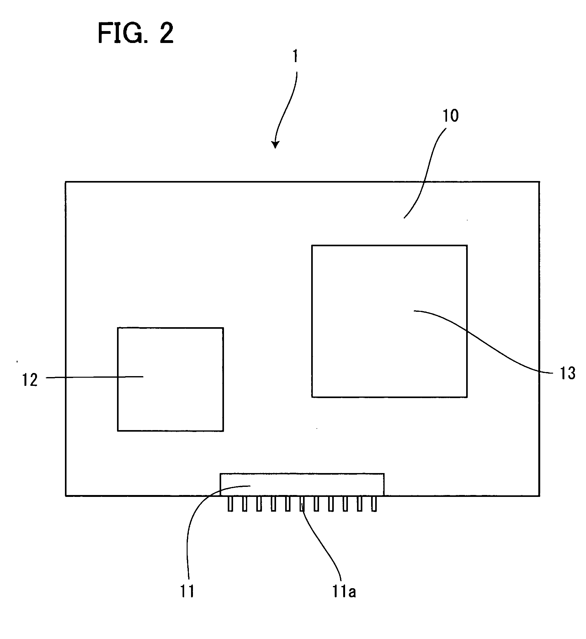
[0025] FIGS. 1 to 4 show the embodiments of the present invention. FIG. 1 is a perspective view showing a configuration of a digital signal demodulation unit according to this embodiment. FIG. 2 is a front view showing the digital signal demodulation unit. FIG. 3 is a plan view showing a state of mounting the digital signal demodulation unit, a digital tuner and other electronic components on a circuit board. FIG. 4 is a plan view of the circuit board showing the reversed state of a right and left positional relation of the digital signal demodulation unit and the digital tuner of FIG. 3.

[0026] FIGS. 5 to 9 show a board layout structure of a digital broadcast receiving portion of the c...


PUM


Abstract

The invention provides a board layout structure of a digital broadcast receiving portion, wherein mutual positional relation between a digital signal demodulation unit and a digital tuner is interchangeable between right and left. An IF input terminal of a digital signal demodulation unit is placed at a center of a connector so that the IF input terminal can be electrically connected to a digital tuner by pattern wiring of fixed length whether the digital tuner is placed to the right or to the left of the digital signal demodulation unit so as to give even digital broadcast receiving performance in either case.

Description

[0001] The present application is based on and claims priority of Japanese patent application No. 2005-354747 filed on Dec. 8, 2005, the entire contents of which are hereby incorporated by reference. BACKGROUND OF THE INVENTION [0002] 1. Field of the Invention [0003] The present invention relates to a board layout structure of a digital broadcast receiving portion, wherein mutual positional relation between a digital signal demodulation unit and a digital tuner is interchangeable between right and left. [0004] 2. Description of the Related Art [0005] Conventionally, various methods are disclosed as to aboard layout structure of a digital tuner and a digital signal demodulation unit necessary for a digital broadcast receiving portion. [0006] For instance, Japanese Patent Laid-Open Publication No. 2002-152063 (Patent Document 1) discloses a method whereby, on placing the digital signal demodulation unit and a tuner unit, their ground patterns are placed to be mutually opposed by conce...

Claims


Application Information

Patent Timeline
Patent Type & Authority Applications(United States)
IPC IPC(8): H04B1/08
CPCH04B1/08
Inventor KATAYAMA, SATOSHI
Owner ORION ELECTRIC CO LTD
Learn More