Hand-guided power tool rotating knob adjusting device

a technology of rotating knob and power tool, which is applied in the direction of portable power tools, hand planes, flat surface machines, etc., to achieve the effect of reducing the risk of unintentional damage to the workpiece being machined

Inactive Publication Date: 2007-07-05
ROBERT BOSCH GMBH
View PDF18 Cites 8 Cited by
  • Summary
  • Abstract
  • Description
  • Claims
  • Application Information

AI Technical Summary

Benefits of technology

[0005]The object of the invention is to disclose a hand-guided power tool embodied in such

Problems solved by technology

The maneuvering forces exerted on the knob part of the rotating knob adjusting device, no

Method used


Image

  • Hand-guided power tool rotating knob adjusting device
  • Hand-guided power tool rotating knob adjusting device
  • Hand-guided power tool rotating knob adjusting device

Examples


Embodiment Construction

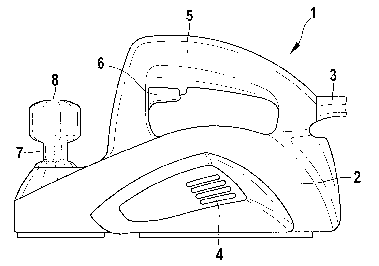
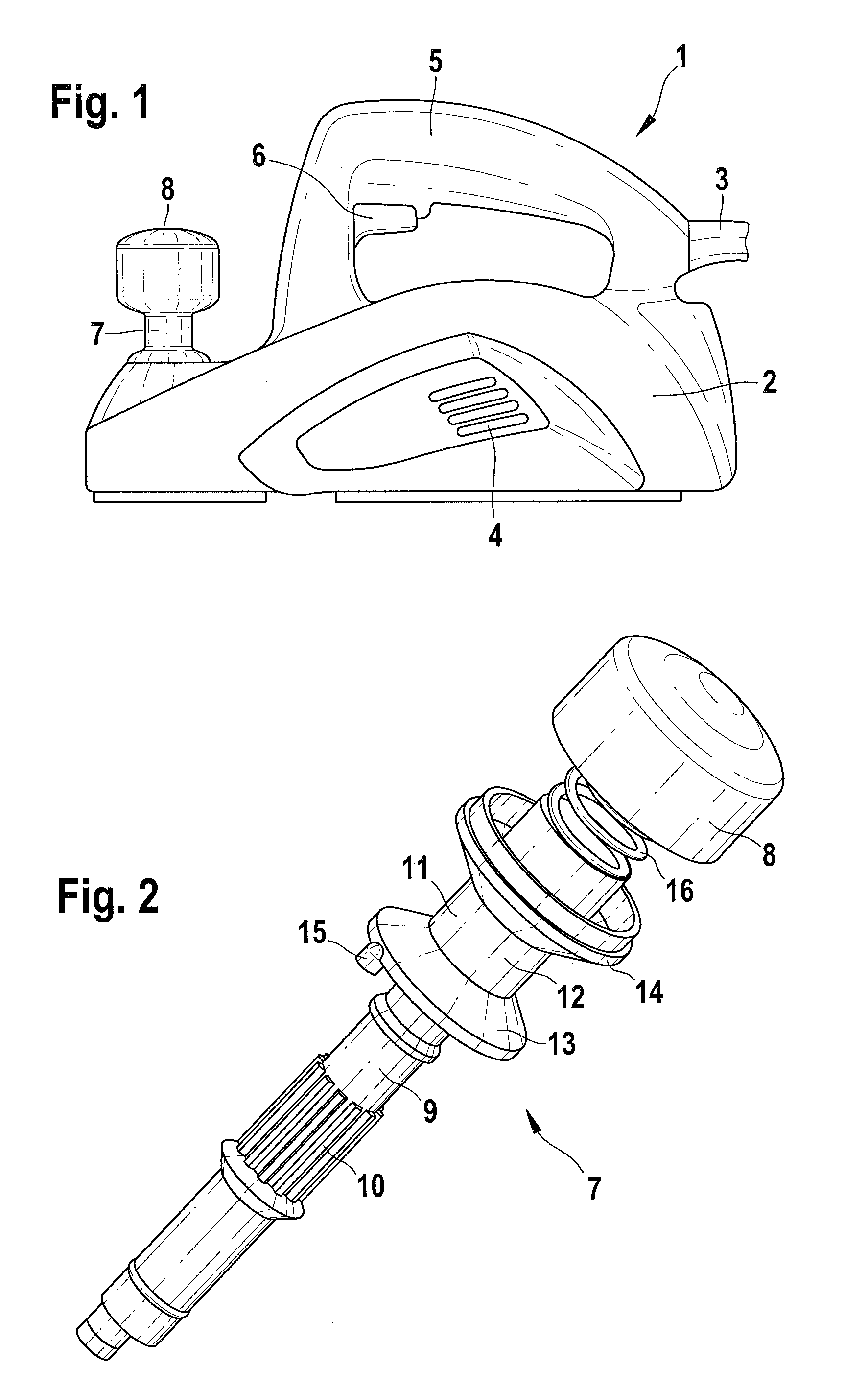
[0023]The hand-guided power planer 1 shown in FIG. 1 has a plastic housing 2. The hand-guided power planer 1 is provided with electrical energy via a cable 3. A drive motor, not shown, is contained inside the housing 2 and is provided to drive a planing shaft that is also not shown. The waste heat from the motor is transported out of the housing 2 via lateral ventilation slots 4. The hand-guided power planer 1 has a handle 5 with a trigger switch 6 for switching the motor on and off. In the front region of the hand-guided power planer 1, there is a rotating knob adjusting device 7 with a knob part 8. The rotating knob adjusting device 7 serves on the one hand as an auxiliary handle for guiding the hand-guided power planer 1 and on the other hand for setting the cutting depth, i.e. to adjust the position, of the planning shaft, not shown.

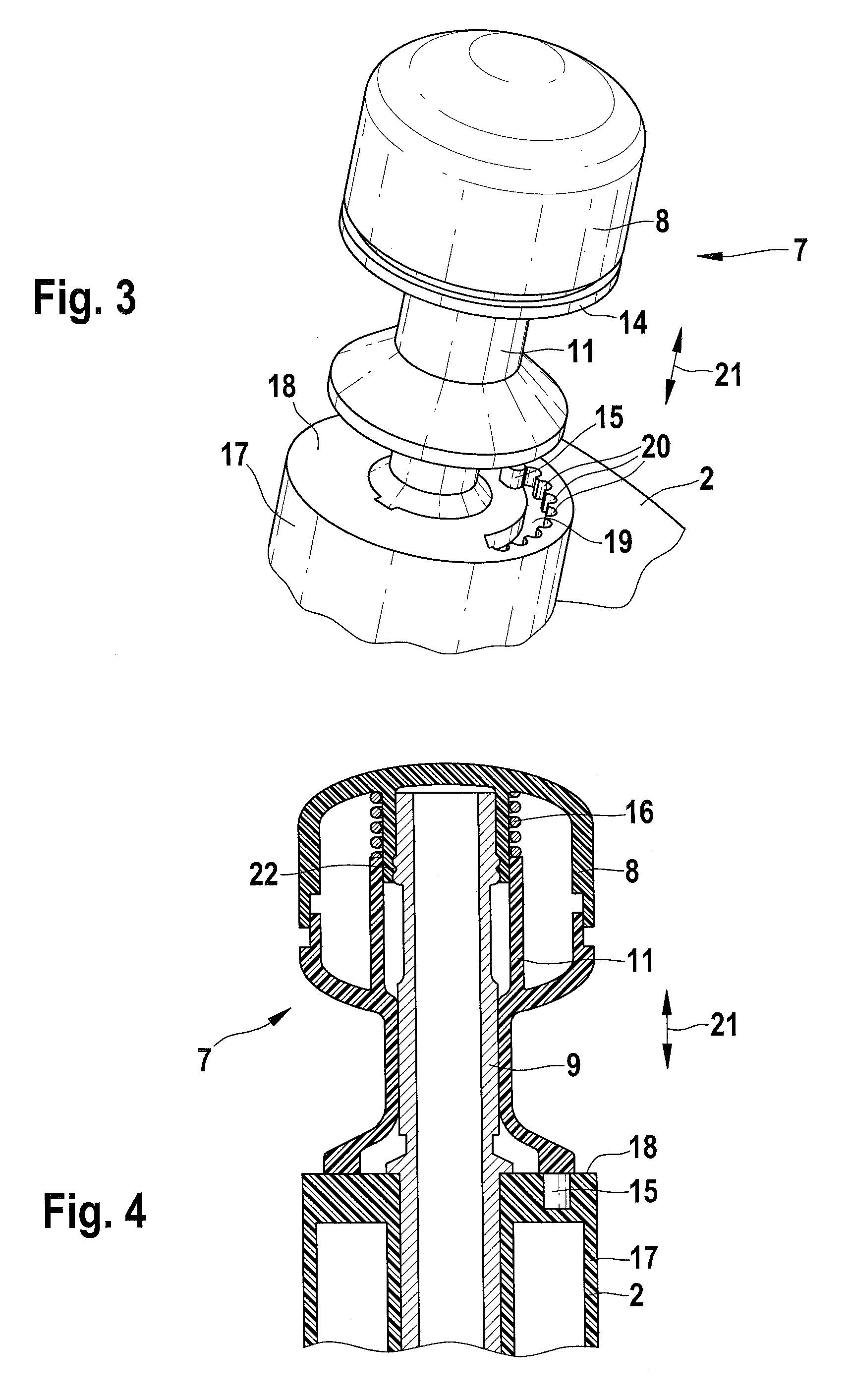
[0024]FIG. 2 shows the rotating knob adjusting device 7 as an uninstalled subassembly. For the sake of visibility, the knob part 8 is shown axially ...


PUM


Abstract

A hand-guided power tool having a rotating knob adjusting device provided with a knob part and rotatable between at least two adjustment positions spaced apart from each other in a circumferential direction, and means for securing the rotating knob adjusting device against an inadvertent rotation.

Description

CROSS-REFERENCE TO A RELATED APPLICATION[0001]The invention described and claimed hereinbelow is also described in German Patent Application DE 10 2005 063 016.2 filed on Dec. 30, 2005. This German Patent Application, whose subject matter is incorporated here by reference, provides the basis for a claim of priority of invention under 35 U.S.C. 119(a)-(d).BACKGROUND OF THE INVENTION[0002]The invention relates to a hand-guided power tool with a rotating knob adjusting device.[0003]Hand-guided power tools of this kind are known in an extremely wide variety of forms. All of the known hand-guided power tools share the common trait that the rotating knob adjusting device on the one hand serves as a grip for absorbing guidance and holding forces during operation of the hand-guided power tool and on the other hand, serves as an adjusting device, for example for changing the operating state of the hand-guided power tool or for adjusting the position of the in particular rotating tool of the ...

Claims


Application Information

Patent Timeline
IPC IPC(8): B27C1/10
CPCB27C1/10B25F5/02
Inventor PAPP, GABORDUDAS, JOZSEF
Owner ROBERT BOSCH GMBH
Why Eureka
Try Eureka