Valve Assembly for Paintball Guns and the Like, and Improved Guns Incorporating the Assembly

Inactive Publication Date: 2007-07-05
LONG ROBERT M
View PDF25 Cites 26 Cited by
  • Summary
  • Abstract
  • Description
  • Claims
  • Application Information

AI Technical Summary

Benefits of technology

[0016]A first object of the invention is to provide a paintball gun which will preferably be capable of firing paint balls at rates measured in the tens of balls per second. A second object of the invention is to lower the size and weight of the gun relative to the prior art. Another object of the present invention is to improve the reliability of successfully firing the gun, and also simultaneously ease gun cleaning when a paint ball is broken within the gun.

Problems solved by technology

These guns, while fully functional and capable of firing projectiles at great speeds, suffered from many significant drawbacks.
Foremost among these was the inability to keep the gun in a ready-to-fire state, commonly due to slow leakage through the pumping mechanisms, and the delay time between firing successive shots, necessitated by the need to pump another charge of air into the pressure chamber after each shot.
In addition, having been designed to resemble the gun powder versions, they were often rather large and heavy.
Common valves required a substantial amount of time to activate and reset, which in view of the relatively small number of shots available was not normally considered a limitation for these guns.
One area of development which has and continues to be very challenging to gun designers is the firing rate of a gun.
Since movement and motion are inseparable from paintball, the higher firing rate translates into a greater likelihood of marking an opponent.
Another demanding area of development is the size and weight of the gun.
The smaller a gun, the more difficult it will be to be marked by an opponent.
When a paint ball breaks within the gun, a way must be provided to remove the components since paint will be smeared or splashed about inside the gun, and without cleaning, will increasingly interfere with proper operation The more readily the components along the path of the ball are removed, the easier and quicker it will be for a participant to recover from a broken ball.
Nevertheless, the precision of components and operation must still be maintained, or there will be many more balls breaking.

Method used


Image

  • Valve Assembly for Paintball Guns and the Like, and Improved Guns Incorporating the Assembly
  • Valve Assembly for Paintball Guns and the Like, and Improved Guns Incorporating the Assembly
  • Valve Assembly for Paintball Guns and the Like, and Improved Guns Incorporating the Assembly

Examples


Embodiment Construction

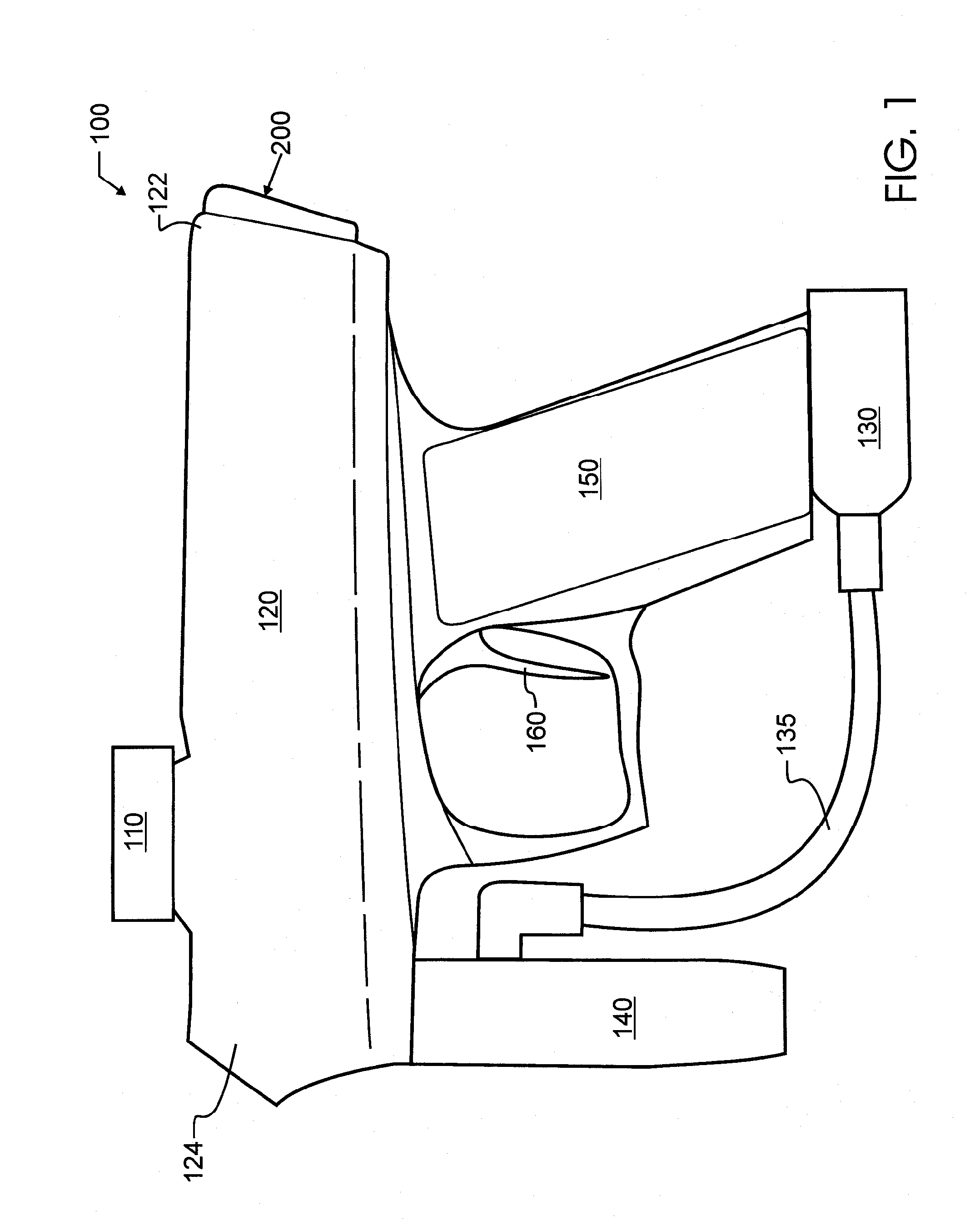
[0023]A paintball gun 100, also referred to as a paintball marker, is shown by an external side plan view in FIG. 1. As illustrated therein, a feed neck 110 is provided for introducing paint balls into gun 100. The source of paint balls is not consequential to the present invention, but may be a magazine such as a hopper, a powered ball feeder, or other device known in the art to provide a high speed, high volume source of paint balls. The paint balls will pass from feed neck 110 into gun body 120, where they will rest in the breech From there, the balls will be moved forward, and then fired, or violently expelled by a high-pressure blast, through barrel coupler 124 and out a gun barrel as is known in the art. A high pressure gas canister is coupled, either directly or indirectly, through coupler 130. High pressure gas will pass from coupler 130 through hose 135 and into pressure regulator 140 for distribution into gun body 120. A handle 150 and trigger 160 provide the human interfa...


PUM


Abstract

A gun preferably designed to rapidly fire paint balls includes a single valve assembly that is inserted into and removed from the gun body. The valve assembly includes a low pressure ram passing through a longitudinal center or core of the assembly, and is capable of being driven in opposite reciprocal directions. A volumizer stores a charge of high pressure gas sufficient to adequately propel a paint ball, and a high pressure poppet valve is driven by movement of the low pressure ram for releasing the charge rapidly. A bolt carried upon the low pressure ram moves a paint ball into firing position just prior to the high pressure discharge. All of the aforementioned components of the cartridge are carried upon a single axis defined by the ram. Means are provided to both align and couple the various components together to ensure proper operation at high firing rates.

Description

CROSS REFERENCE TO RELATED APPLICATIONS[0001]This application claims priority to U.S. provisional patent application Ser. No. 60 / 729,814 filed Oct. 22, 2005 entitled “Pneumatic Sleeve, Hammer and Valve Assembly for Paintball Guns and the Like, and Improved Guns Incorporating the Assembly” naming the present inventor, and to U.S. provisional patent application Ser. No. 60 / 762,969 filed Jan. 26, 2006 also entitled “Pneumatic Sleeve, Hammer and Valve Assembly for Paintball Guns and the Like, and Improved Guns Incorporating the Assembly” and naming the present inventor, the contents of each which are incorporated herein by reference in entiretyBACKGROUND OF THE INVENTION[0002]1. Field of the Invention[0003]This invention pertains generally to the field of mechanical guns and projectors, and more particularly to fluid pressure propulsion, with control for discharge of fluid pressure provided by a valve. In a preferred embodiment, the present invention is manifested in a single-axis bolt ...

Claims


Application Information

Patent Timeline
IPC IPC(8): F41B11/00
CPCF41B11/721
Inventor LONG, ROBERT M.
Owner LONG ROBERT M
Why Eureka
Try Eureka