Composite fiber component produced by braiding

Active Publication Date: 2007-07-05
EADS DEUT GMBH
View PDF13 Cites 26 Cited by
  • Summary
  • Abstract
  • Description
  • Claims
  • Application Information

AI Technical Summary

Benefits of technology

[0027] For this purpose, a braided fiber composite tube is preferably used, which is pulled over the at least one holding element in the manner of a stocking, before the stacking or placing of the core elements. This fiber composite tube can, in turn, be produced by means of the initially mentioned circular braiding technique by using carbon, glass and/or aramid fibers (as required, with corresponding supporting threads). However, the holding element can also be provided with the fiber composite material by the winding around or placing around of corresponding fibers or fabrics. In some cases, it is advantageous to compact (that is, condense,

Problems solved by technology

A disadvantage of such components produced by means of TFP (tailored fiber placement), however, is that only a small component thickness can be obtained, because the embroidering base has negative effects on the mechanical characteristics of the component, particularly due to lateral contractions during tension or compression loads.
However, in this case only a single component can be produced, and winding is a high-expenditure process.
In addition, when winding at non-zero angles,

Method used


Image

  • Composite fiber component produced by braiding
  • Composite fiber component produced by braiding
  • Composite fiber component produced by braiding

Examples


Example

DETAILED DESCRIPTION OF THE DRAWINGS

[0048] In the figures, identical or similar components have identical reference numbers. The representations in the figures explain the fiber composite component purely schematically and may partly not be true to scale.

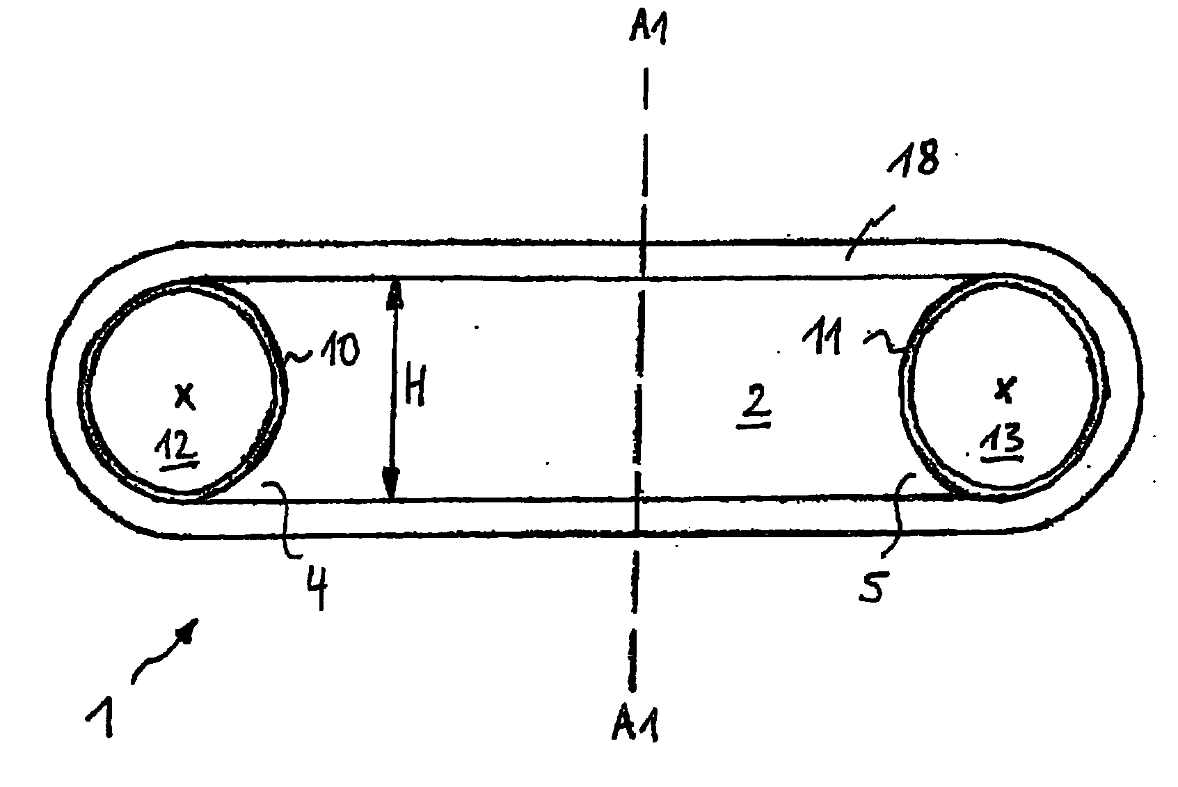
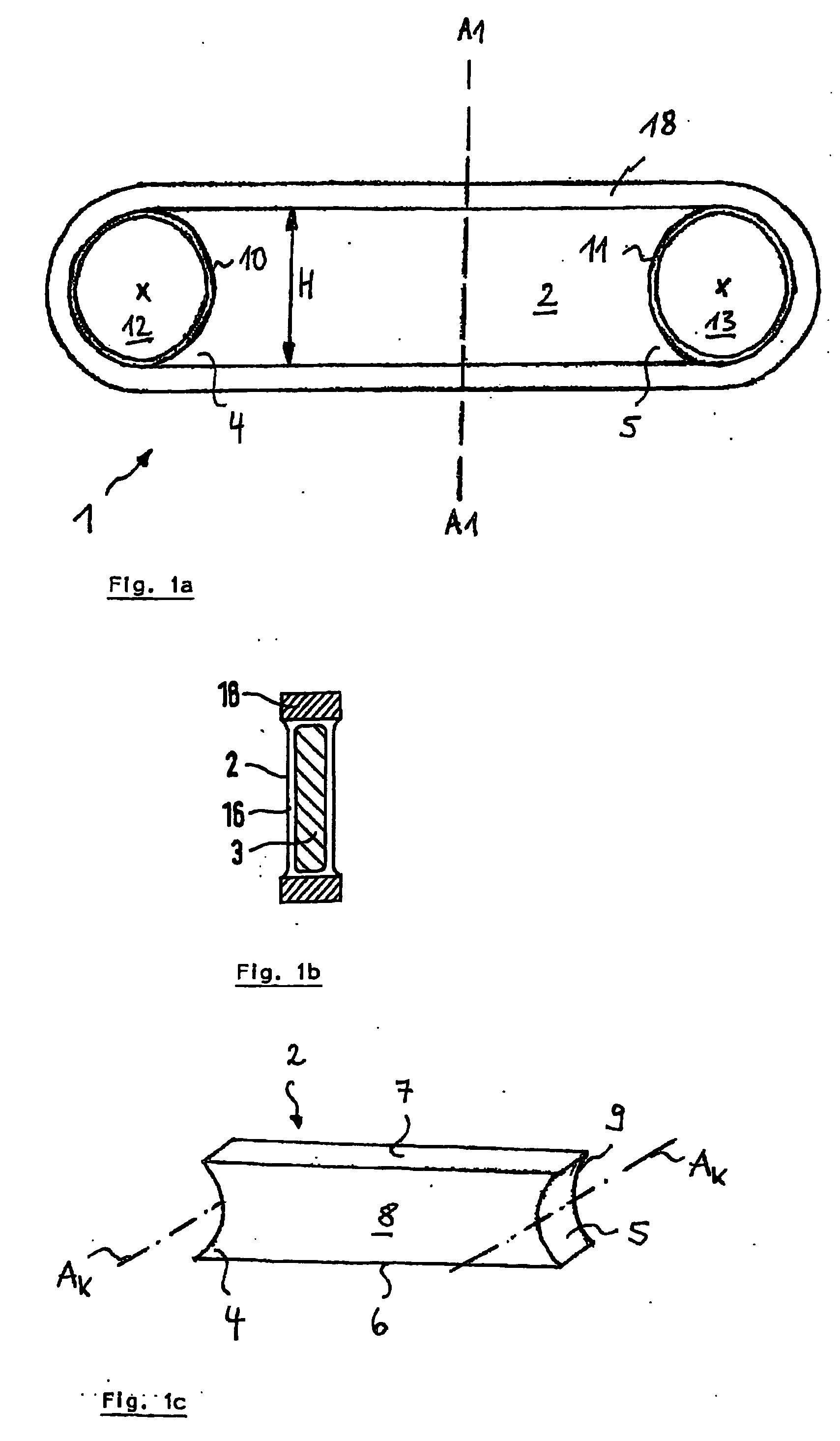
[0049]FIG. 1a illustrates a preferred embodiment of the fiber composite component 1 according to the invention, which comprises a core element 2 whose faces 4, 5 are concavely constructed with a defined radius of curvature. This is also illustrated in FIG. 1c, which is a schematic three-dimensional representation of a rectangular parallelepiped shaped core element 2 with corresponding transverse sides 6, 7 and longitudinal sides 8, 9. The axis of curvature of the concavity Ak extends perpendicular to the longitudinal sides 8, 9 and is illustrated in FIG. 1c by a dash-dotted line. Correspondingly, the axis of curvature of the concavity Ak is perpendicular to the plane of the drawing of FIG. 1a, and is indicated by an “x”.

[0050] As...


PUM

PropertyMeasurementUnit
Angleaaaaaaaaaa
Angleaaaaaaaaaa
Radiusaaaaaaaaaa

Abstract

A fiber composite component is at least partially produced by braiding. It comprises a core element which has at least one concavely constructed face that is adjoined by a passage opening. Respective opposite transverse or longitudinal sides of the core element and the side of the passage opening not bounded by the core element are enclosed by a braided fiber composite loop element.

Description

BACKGROUND AND SUMMARY OF THE INVENTION [0001] This application claims the priority of German patent document 10 2005 059 933.8-16, filed Dec. 13, 2005, the disclosure of which is expressly incorporated by reference herein. [0002] The present invention is directed to a fiber composite component that is at least partially produced by braiding, particularly a compression-tension strut, and to a method of producing such fiber composite components. The invention also includes an aircraft having such a compression-tension strut or fiber composite component. [0003] Fiber composite components are used in aerospace engineering and in automotive engineering, to save weight. For this purpose, construction types consisting of CFRPs (carbon fiber reinforced plastic) have been developed to replace previous metallic components (joining elements, transverse links, etc.) with fiber composite components. For example, numerous commercial aircraft currently use metallic rear links for the bearing of l...

Claims


Application Information

Patent Timeline
IPC IPC(8): B64C9/00
CPCB29C70/222B29C70/48B29C70/545B29C70/86B29C2793/009B29K2105/08Y10T428/233B29L2031/3076B29L2031/75F16C7/02F16C7/026Y02T50/433Y10T428/2936B29K2105/20B29L2031/737Y02T50/40Y10T428/249924Y10T428/249981
Inventor FILSINGER, JUERGENHAVAR, TAMASMAIDL, FRANZSCHOUTEN, MARINUS
Owner EADS DEUT GMBH
Why Eureka
Try Eureka