
Method and apparatus providing color interpolation in color filter arrays using edge detection and correction terms

a color filter array and color filter technology, applied in the field of color filter array color interpolation using edge detection and correction terms, can solve the problems of image blur, image may suffer from the inclusion of highly visible color artifacts, artifacts such as so-called zipper effect and random color dots, etc., and achieve the effect of reducing some of the disadvantages of image sharpness loss

Active Publication Date: 2007-07-05
MICRON TECH INC
View PDF12 Cites 29 Cited by
  • Summary
  • Abstract
  • Description
  • Claims
  • Application Information

AI Technical Summary

Benefits of technology

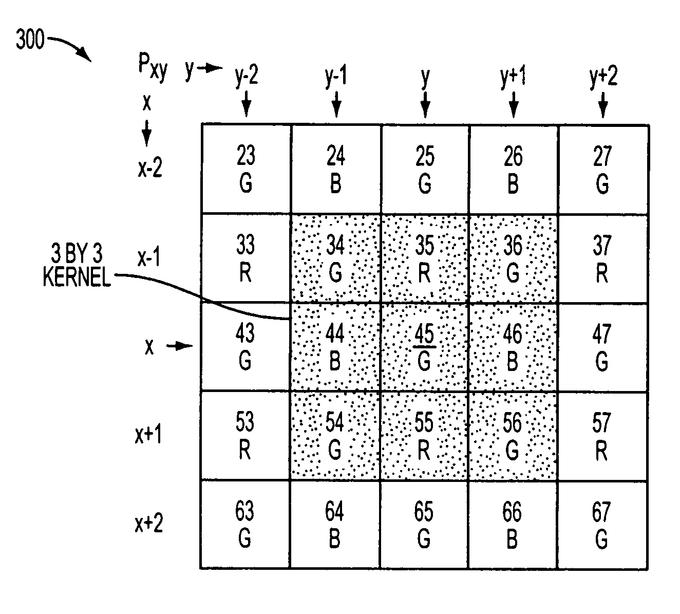
[0013] A method and apparatus for color plane interpolation are provided which interpolates the color values of pixels differently depending on an edge direction and whether a pixel is at an edge within an image. The use of the edge detection during the interpolation of each of the colors present in the color pattern helps reduce some of the disadvantages of the loss of image sharpness abundant in known demosaicing techniques.

Problems solved by technology

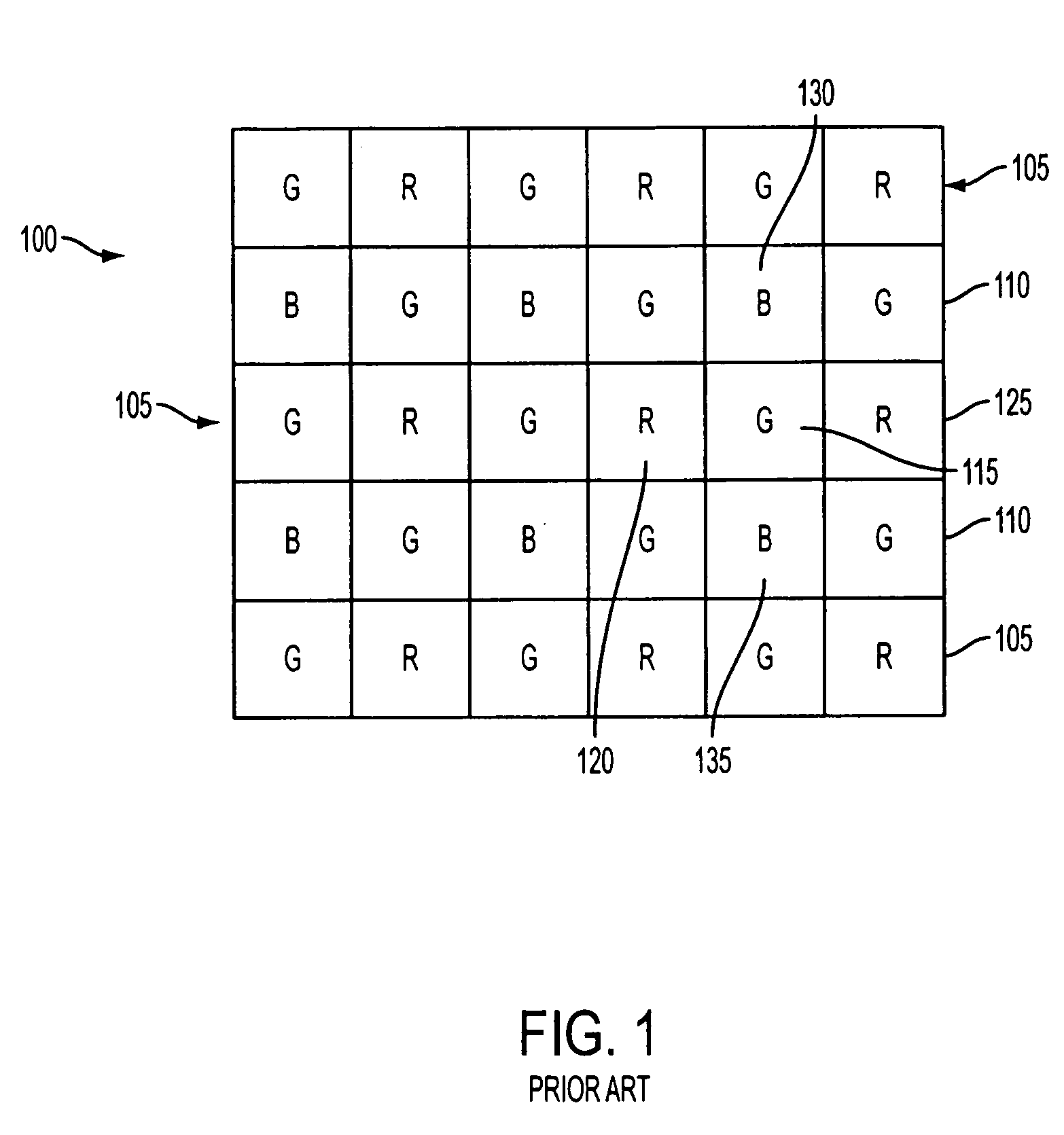
If demosaicing is not performed correctly, the resulting image may suffer from the inclusion of highly visible color artifacts.
Demosaicing methods, which typically only reconstruct the missing color components, may result in artifacts such as so-called zipper effects and random color dots.
Additionally, there exists a trade off between filtering for noise and the blurring of sharp edges.
Interpolating a pixel using the surrounding pixel values tends to blur the image when pixels at an edge are interpolated.
Furthermore, this also leads to a decrease in the sharpness of the image at the edges.
The demosaicing method averages pixels so that a pixel at an edge does not have the sharpness desired of an edge pixel.

Method used


Image

  • Method and apparatus providing color interpolation in color filter arrays using edge detection and correction terms
  • Method and apparatus providing color interpolation in color filter arrays using edge detection and correction terms
  • Method and apparatus providing color interpolation in color filter arrays using edge detection and correction terms

Examples


Embodiment Construction

[0022] In the following detailed description, reference is made to the accompanying drawings which form a part hereof, and in which is shown by way of illustration specific embodiments in which the invention may be practiced. These embodiments are described in sufficient detail to enable those skilled in the art to practice the invention, and it is to be understood that other embodiments may be utilized, and that structural, logical and electrical changes may be made without departing from the spirit and scope of the present invention.

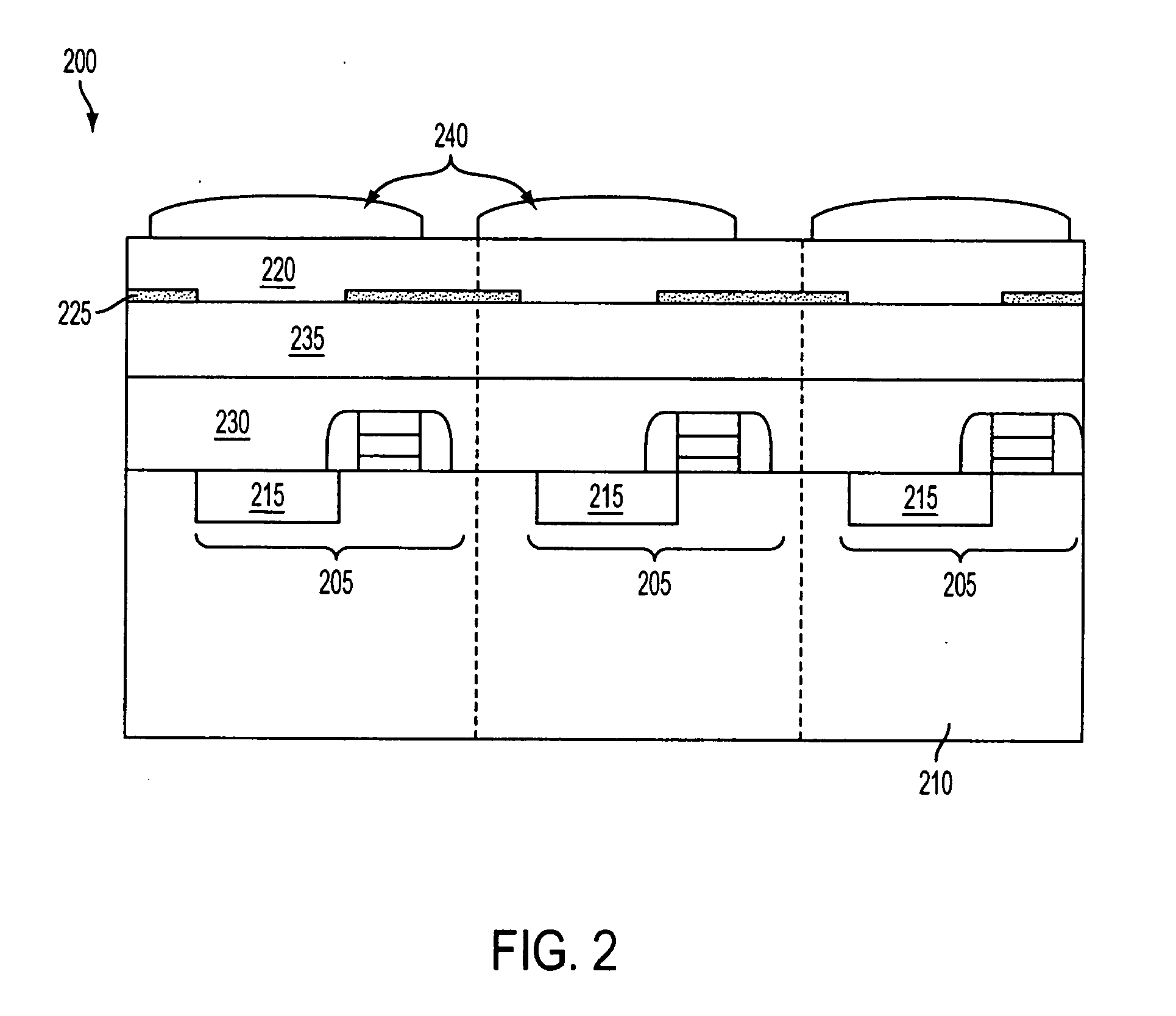
[0023] The term “pixel” refers to a picture element unit cell containing a photosensor and transistors for converting light radiation to an electrical signal. For purposes of illustration, a representative pixel is illustrated in the figures and description herein and, typically, fabrication of all pixels in an imager will proceed simultaneously in a similar fashion. The following detailed description is, therefore, not to be taken in a limiting sense...


PUM


Abstract

A method and apparatus for color plane interpolation are provided which interpolates the color values of pixels differently depending on an edge direction and whether a pixel is at an edge within an image. The use of the edge detection during the interpolation of each of the colors present in the color pattern helps reduce some of the disadvantages of the loss of image sharpness abundant in known demosaicing techniques.

Description

[0001] The present invention relates to demosacing for use on an image captured by an image sensor. BACKGROUND OF THE INVENTION [0002] Image sensors, also known as imagers, were developed in the late 1960s and early 1970s primarily for television image acquisition, transmission, and display. An imager absorbs incident radiation of a particular wavelength (such as optical photons, x-rays, or the like) and generates an electrical signal corresponding to the absorbed radiation. There are a number of different types of semiconductor-based imagers, including charge coupled devices (CCDs), photodiode arrays, charge injection devices (CIDs), hybrid focal plan arrays, and CMOS imagers. [0003] These imagers typically consist of an array of pixels containing photosensors, where each pixel produces a signal corresponding to the intensity of light impinging on that element when an image is focused on the array. These signals may then be stored, for example, to display a corresponding image on a...

Claims


Application Information

Patent Timeline
Patent Type & Authority Applications(United States)
IPC IPC(8): H04N9/04H04N23/12H04N25/00
CPCG06T3/4015H04N9/045H01L27/14645H01L27/14621H04N23/843H04N25/134H04N23/10
Inventor SUBBOTIN, IGOR
Owner MICRON TECH INC
Learn More