
Optical measuring device for measuring a cavity

a measuring device and optical technology, applied in the field of optical measuring devices, can solve the problems of low spatial and depth resolution, low measurement rate of measuring machines of this kind, and conventionally very low measurement rate, and achieve the effect of rapid and precise measuremen

Inactive Publication Date: 2007-07-05
SIEMENS AG
View PDF17 Cites 65 Cited by
  • Summary
  • Abstract
  • Description
  • Claims
  • Application Information

AI Technical Summary

Benefits of technology

[0008] The object underlying the invention is to provide an optical measuring device for measuring the inner wall of a cavity formed in an object, which measuring device allows rapid and, at the same time, precise measurement.

Problems solved by technology

The cylindrical drill holes are measured nowadays by means of capacitive measuring methods which, however, are very unreliable and have low spatial and depth resolutions.
The measuring rate of measuring machines of this kind is conventionally very low, however.
However, the method of impression taking has the drawback that the auricular canal is not directly measured but only indirectly by way of a measurement of the impression.
This leads to inaccuracies in the hearing aids produced and to accordingly reduced wearing comfort.

Method used


Image

  • Optical measuring device for measuring a cavity
  • Optical measuring device for measuring a cavity
  • Optical measuring device for measuring a cavity

Examples


Embodiment Construction

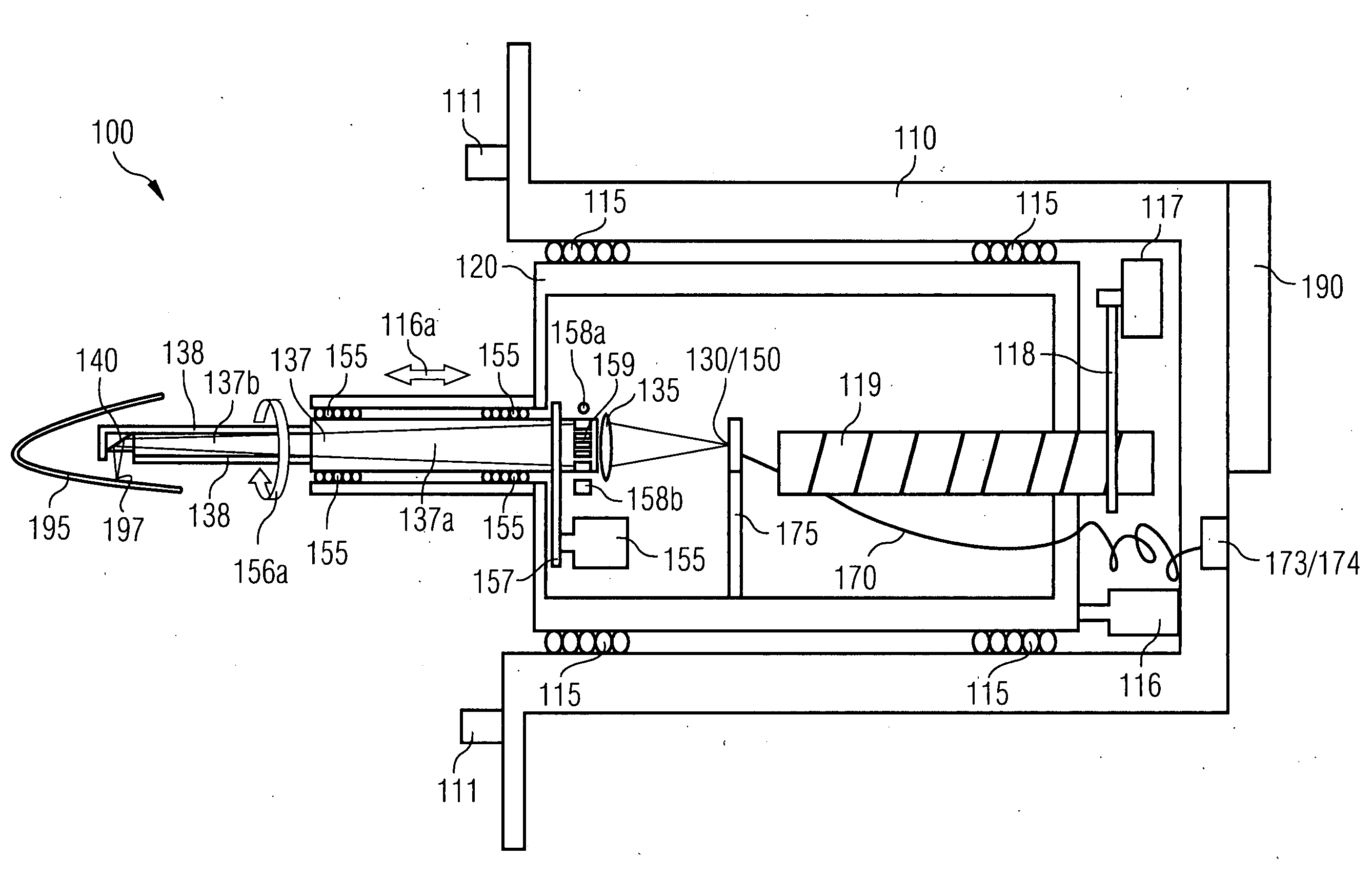
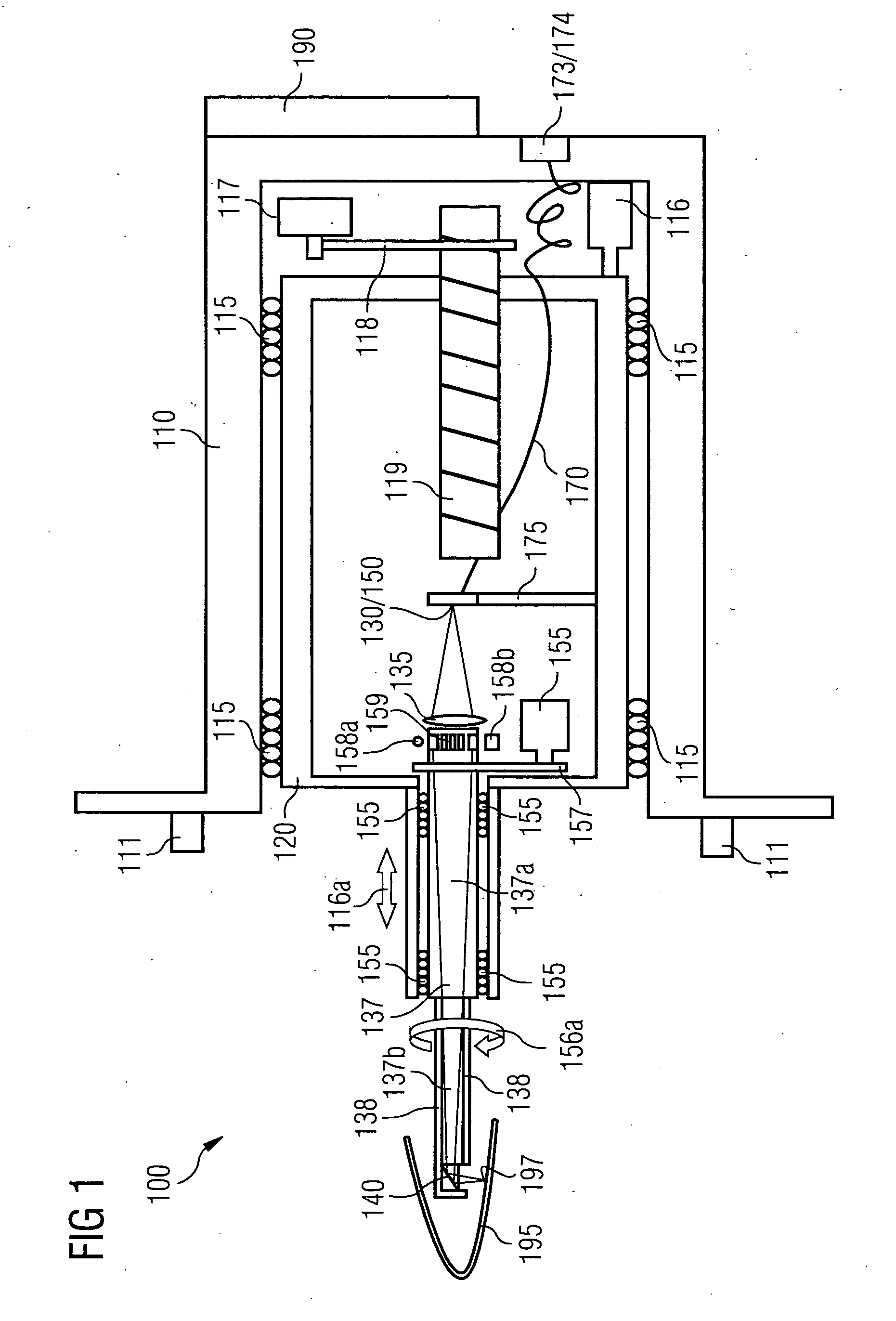
[0047]FIG. 1 shows a confocal measuring device 100 comprising what is known as a chromatic confocal proximity sensor. The measuring device 100 illustrated here is used to measure the auditory canal of an auricle 195. Spatial data of the inner structure of the auditory canal can be ascertained in the process, so a precisely fitting hearing aid may be produced.

[0048] The measuring device 100 comprises a housing 110 on which adaptation elements 111 are provided which allow defined positioning of the housing 110 on the side of a patient's head (not shown). Provided in the housing 110 is a measuring head 120 in which the actual chromatic confocal proximity sensor is constructed. The measuring head 120 is axially displaceably mounted relative to the housing 110, so the measuring head 120 can be positioned relative to the housing 110 along a direction of displacement 116a by means of an axial drive 116. To ensure defined axial displacement of the measuring head 120 a plurality of linear b...


PUM


Abstract

An optical measuring device for measuring an inner wall of a cavity has a confocal proximity sensor. The beam path of the illumination light and the measuring light is deflected by a rotatably mounted reflector. By introducing an object-side end of the measuring device into the cavity a peripheral side wall of the cavity is measured. The reflector is rotated about an axis of rotation which coincides with the longitudinal axis of the optical measuring device. The inner wall is scanned along a line that revolves around the axis of rotation. The optical measuring device is equipped with two confocal proximity sensors. At the object-side end of the measuring device dual optics with a plurality of optical components are provided, by which the illumination beams of the two confocal proximity sensors are focused diametrically outwards at mutually opposing scanning points on the inner wall of the cavity.

Description

BACKGROUND OF THE INVENTION [0001] The invention relates to an optical measuring device for measuring the inner wall of a cavity formed in an object according to the confocal imaging principle. The invention relates in particular to an optical measuring device of this type for measuring a cylindrical drill hole and / or for measuring the auricular canal of a human or animal organism. [0002] When producing aircraft a large number of individual joins are necessary to connect different components of an aircraft to each other. Thus for example supporting surfaces are fastened to the aircraft fuselage by means of a large number of riveted joints. Since the precision of the joins has to be extremely high for safety reasons the drilling operations required for a riveted joint must be carried out with a high degree of accuracy, so an optimally fitting rivet may always be used for the respective drill hole. Owing to the size of the individual components that are to be joined together the drill...

Claims


Application Information

Patent Timeline
Patent Type & Authority Applications(United States)
IPC IPC(8): G01B11/24
CPCA61B5/0068A61B5/0084G01B2210/50G01B11/24G01N21/954A61B5/1076
Inventor SCHICK, ANTON
Owner SIEMENS AG
Features
  • Generate Ideas
  • Intellectual Property
  • Life Sciences
  • Materials
  • Tech Scout
  • Unparalleled Data Quality
  • Higher Quality Content
  • 60% Fewer Hallucinations
Learn More