Image processing apparatus, image processing method, and image processing program

Active Publication Date: 2007-07-05
FUJITSU CONNECTED TECH LTD
View PDF13 Cites 5 Cited by
  • Summary
  • Abstract
  • Description
  • Claims
  • Application Information

AI Technical Summary

Benefits of technology

[0030] (1) An image processing apparatus, an image processing method, or an image processing program according to the present invention provides a pseudo-image with an enlarged resolution variation against an actual image obtained by an image-capturing element during focusing operation of an optical system. This makes clear an image variation, which gives a user a sense of the completion of focusing, thus allows the user to feel a real pleasure in photographing.
[0031] (2) The image processing apparatus, the image processi

Problems solved by technology

Less variation in an image gives the user no sense of the completi

Method used


Image

  • Image processing apparatus, image processing method, and image processing program
  • Image processing apparatus, image processing method, and image processing program
  • Image processing apparatus, image processing method, and image processing program

Examples


Example

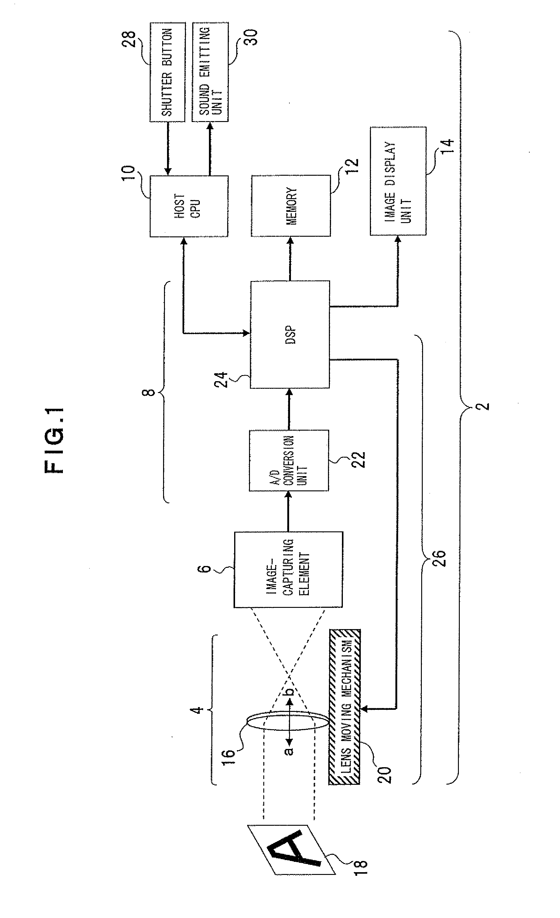
[0050] A first embodiment of the present invention will now be described with reference to FIG. 1. FIG. 1 is a block diagram of an image processing apparatus according to the first embodiment.

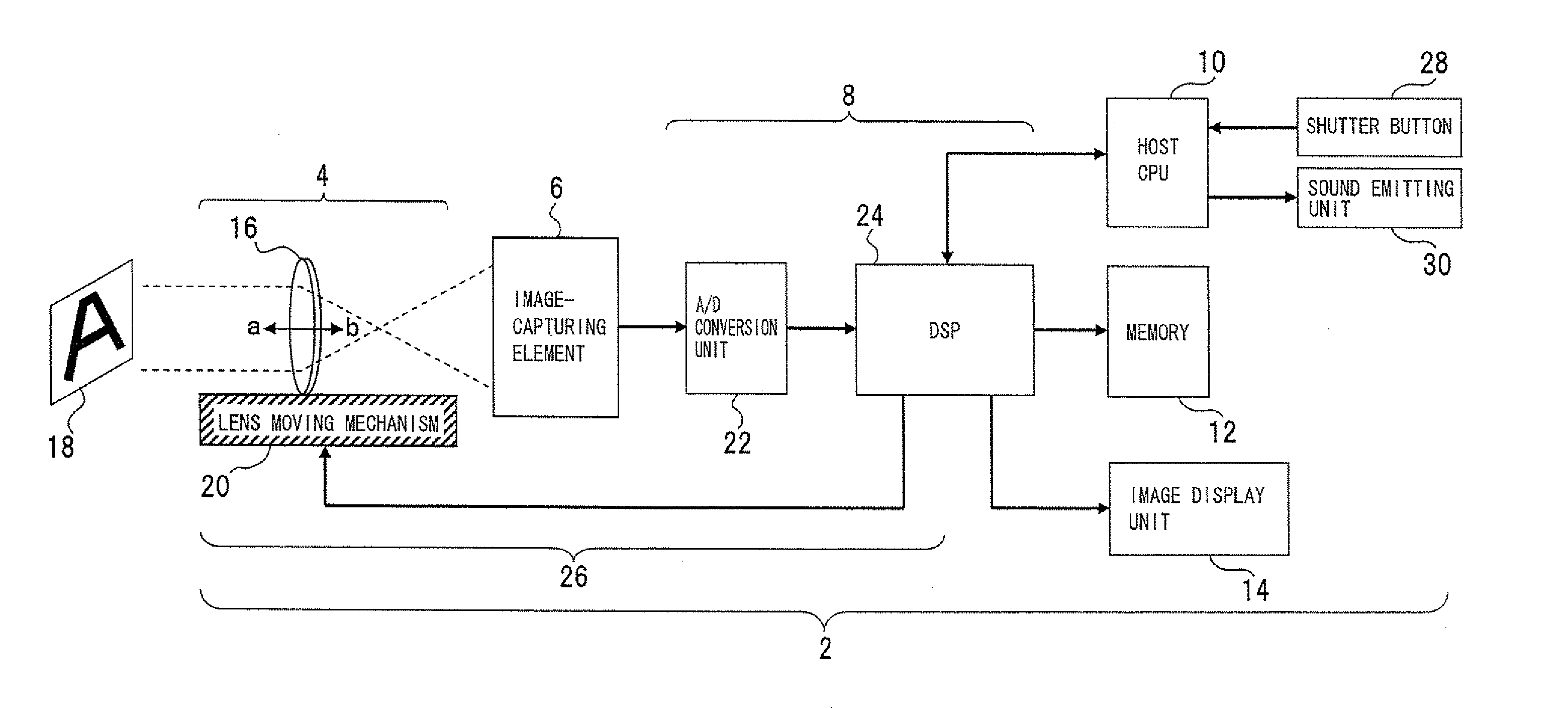
[0051] The image processing apparatus 2, which is an AF camera, etc., includes an optical system 4, an image-capturing element 6, an image processing unit 8, a host CPU (Central Processing Unit) (hereinafter “CPU”) 10, a memory 12, and an image display unit 14. According to the image processing apparatus 2, an image formed on the image-capturing element 6 through the optical system 4 and a pseudo-image, which will be explained later, are displayed on the image display unit 14.

[0052] The optical system 4 has a lens 16, etc., and converges light from a photographed subject 18 through the lens 16 to form an image of the photographed subject 18 on an image-capturing face of the image-capturing element 6. A lens moving mechanism 20 incorporated into the optical system 4 moves the lens 16 to a focu...

Example

Second Embodiment

[0077] A second embodiment of the present invention will be described with reference to FIG. 5. FIG. 5 is a block diagram of an image processing apparatus according to the second embodiment. In FIG. 5, the same components as shown in FIG. 1 are denoted by the same reference numerals.

[0078] The second embodiment exhibits the specific structure of the DSP 24 of the image processing apparatus 2 according to the first embodiment.

[0079] A digitized image is put into the DSP 24 through the A / D conversion unit 22. The image is sent to a contrast detecting unit 44, and to a pseudo-image processing unit 46 via a sensor interface (IF) 38, an image process unit 40, and a function controlling unit 42, and is also sent to the memory 12 through a digital interface (IF) 48. The sensor IF 38 is an input unit that receives an image signal from the A / D conversion unit 22, serving as a buffer for image signal input to the image process unit 40. The function controlling unit 42 is c...

Example

Third Embodiment

[0090] A third embodiment of the present invention will be described with reference to FIG. 8. FIG. 8 is a block diagram of an image processing apparatus according to a third embodiment. In FIG. 8, the same components as shown in FIG. 1 are denoted by the same reference numerals.

[0091] According to the image processing apparatus 2 of the first embodiment, the DSP 24 executes the pseudo-image forming process. According to the image processing apparatus 2 of the second embodiment, the DSP 24 has the pseudo-image processing unit 46 incorporated therein. In contrast, according to the third embodiment, as shown in FIG. 8, the pseudo-image processing unit 46 is disposed outside the DSP 24 to be interposed between the DSP 24 and the image display unit 24. When the pseudo-image processing unit 46 is disposed outside the DSP 14, an image formed on the image-capturing element 6 is put into the pseudo-image processing unit 46 via the DSP 24 to display a pseudo-image as descri...


PUM


Abstract

An image processing apparatus, an image processing method, and an image processing program are provided. The processing apparatus, method, and program relate to image processing executed in an AF camera, etc., and make clear a variation in an image displayed during focusing operation. The image processing apparatus includes an image-capturing element that puts out an image formed through an optical system, a focus controlling unit that controls the optical system to locate it at a focusing position, using the image obtained by the image-capturing element through the optical system, and an image processing unit that forms a pseudo-image during focusing operation of the optical system caused by the focus controlling unit, the pseudo-image showing a resolution variation enlarged to be greater than that of the image obtained by the image-capturing element.

Description

CROSS-REFERENCE TO RELATED APPLICATIONS [0001] This application is a continuation of International Application No. PCT / JP2004 / 013365, filed on Sep. 14, 2004, now pending, herein incorporated by reference.BACKGROUND OF THE INVENTION [0002] 1. Field of the Invention [0003] The present invention relates generally to image processing executed in an autofocus camera, etc., and more particularly, to an image processing apparatus, an image processing method, and an image processing program that allow visual recognition of focusing operation through an image. [0004] 2. Description of the Related Art [0005] In autofocusing (AF) operation carried out in a camera, a digital camera, etc., incorporated into a cellular phone, a portable information terminal unit (PDA: Personal Digital Assistance), etc., a lens moving mechanism is driven by a motor to move a lens physically to change its position and look for a focusing position, so that the lens is fixed at an optimum focusing position. As this f...

Claims


Application Information

Patent Timeline
IPC IPC(8): G03B17/00H04N5/262
CPCH04N5/23293H04N5/23212H04N23/673H04N23/63
Inventor SAIJO, MASASHIMIYAZAKI, KIYOSHIHARUKI, KENICHI
Owner FUJITSU CONNECTED TECH LTD
Why Eureka
Try Eureka