Apparatus Of Driving Lens For Focusing

Inactive Publication Date: 2007-07-05
TOPRAY MEMS
View PDF2 Cites 5 Cited by
  • Summary
  • Abstract
  • Description
  • Claims
  • Application Information

AI Technical Summary

Benefits of technology

[0004] The present invention has been made to overcome the above-mentioned drawback of conventional apparatus for driving lens for focusing. The primary object of the present invention is to provide an apparatus for dr

Problems solved by technology

The current approach to control the focus of the lens in a mobile pho

Method used


Image

  • Apparatus Of Driving Lens For Focusing
  • Apparatus Of Driving Lens For Focusing
  • Apparatus Of Driving Lens For Focusing

Examples


Embodiment Construction

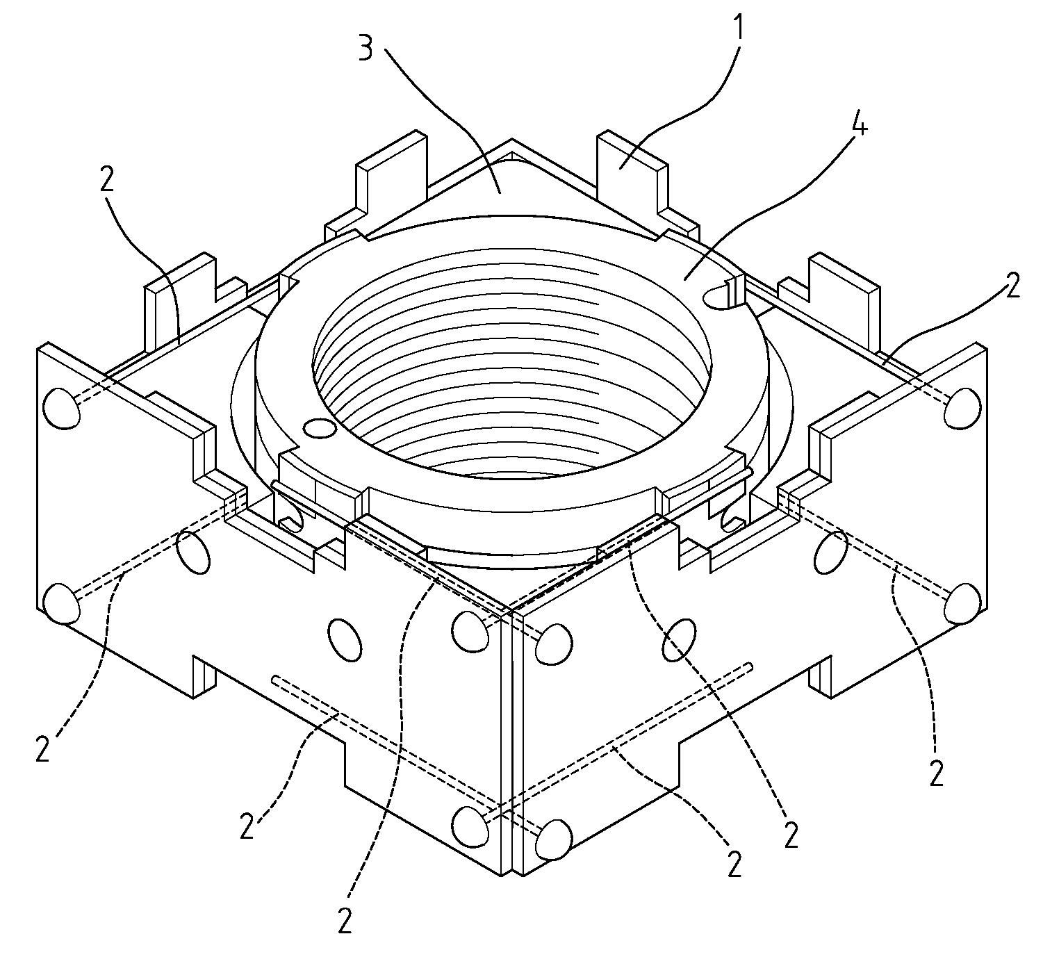
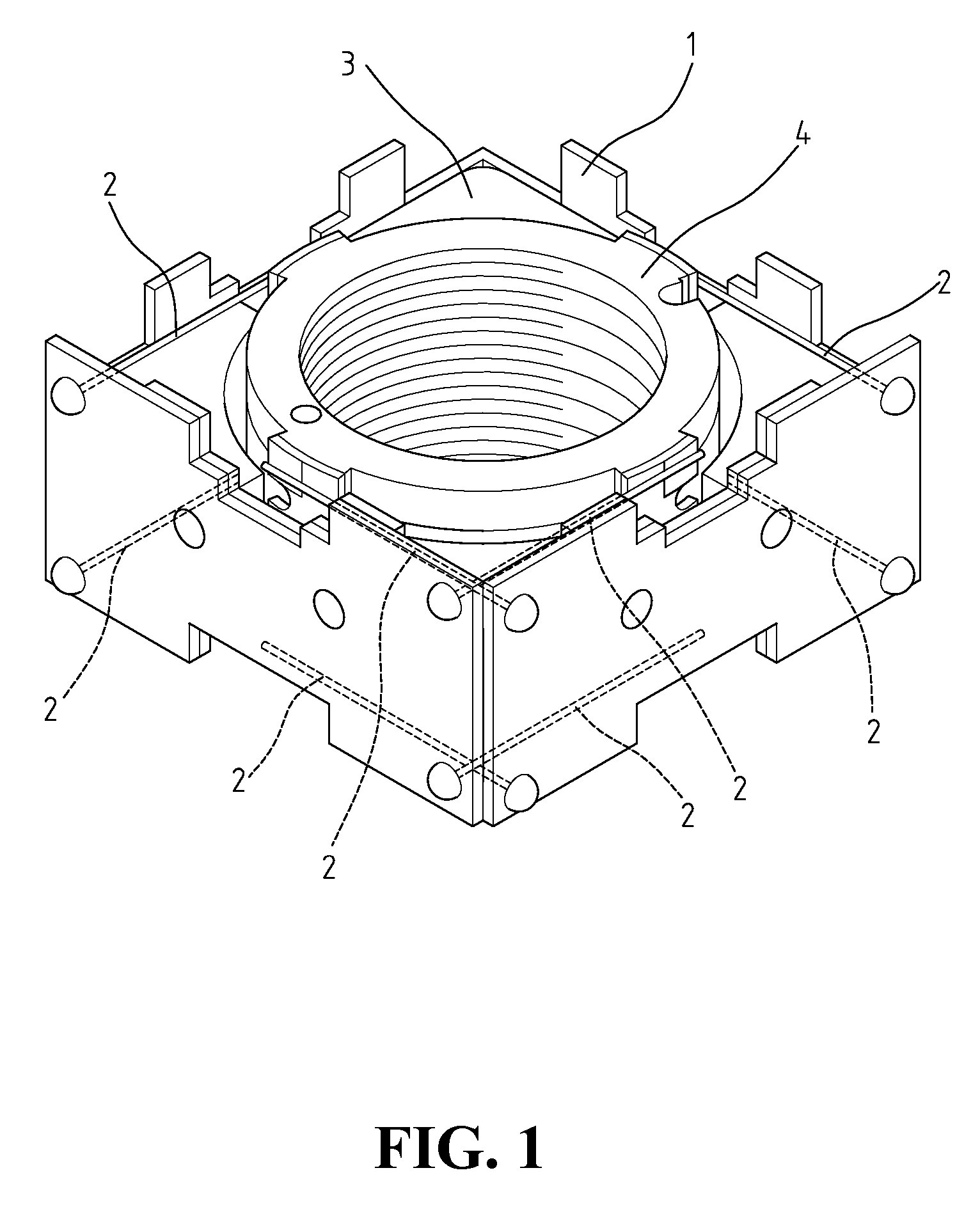
[0014]FIG. 1 shows the three-dimensional view of the present invention, including an outer-holder 1, a wire set 2, a magnet set 3, and an inner-holder 4. Wire set 2 is placed inside outer-holder 1, and indicated as dash line to show the location inside outer-holder 1.

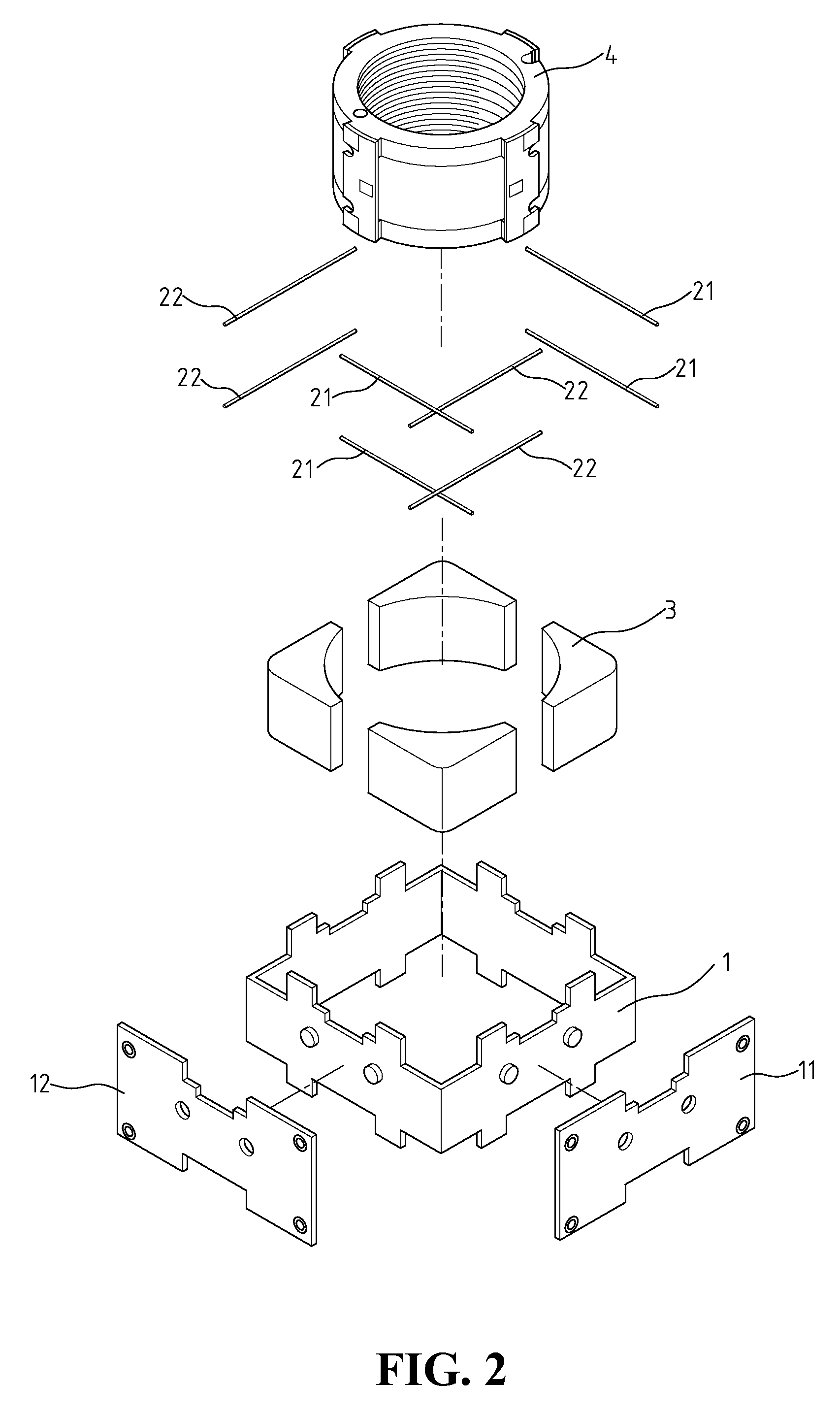
[0015]FIG. 2 shows an exploded view of FIG. 1. Outer-holder 1 further includes a pair of printed circuit board (PCB) 11, 12, used as a fixed end of wire set 2. Wire set 2 include a plurality of wires. The wires are divided into at least two groups, with all the wires in a group are arranged in parallel. Each wire group must include at least two wires. The embodiment in FIG. 2 shows that 8 wires are used, and divided into two groups 21, 22, with each group having four wires. Magnet set 3 is attached or fixed at the corners inside outer holder 1, as shown in FIG. 3. The hollow of inner-holder 4 is for housing a lens. Inner holder 4 is covered with a coil 41 and a plurality of PCB 42 on the outer surface, as shown in FIG....


PUM


Abstract

An apparatus of auto-focusing is provided, including an outer holder, a wire set, a magnet set and an inner-holder. The magnet set is fixed at the corners inside the outer-holder. The inner-holder is a hollow cylinder surrounded by a coil. The wire set is connected to the top and the bottom ends of the outer-holder. The other end of the wire set is connected to the outer circumference of the inner-holder. Therefore, the inner-holder is a hanging moveable component, which can move vertically when the electrical current flows through the coil to achieve the object of auto-focusing.

Description

FIELD OF THE INVENTION [0001] The present invention generally relates to an apparatus for lens of mobile phones, and more specifically to an apparatus for counteracting the gravity effect when driving the lens of mobile phones for auto-focusing. BACKGROUND OF THE INVENTION [0002] The mobile phones bring much convenience to the people for long distance communication. As the technology progresses, more and more functions are added to the mobile phones. In addition to the audio communication, functions, such as photography, audio recording, music playing, and video viewing, are all added to list of options of mobile phones. Some of the above functions, such as photography, are so common that they are becoming an integral part of a mobile phone. More and more users are using their mobile phone as a camera. Therefore, improved functions, such as high-pixel pictures and auto-focusing, are considered as essential to the ease of use while posing severe restriction on the thin design of the ...

Claims


Application Information

Patent Timeline
IPC IPC(8): G03B3/10
CPCG03B29/00G03B3/10
Inventor CHUNG, YU-FENCHANG, TSUNG-KAILIU, CHIN-SUNG
Owner TOPRAY MEMS
Why Eureka
Try Eureka