Percutaneous atrioventricular valve and method of use

a technology of atrioventricular valve and atrioventricular valve, which is applied in the field of applicator and method of replacing atrioventricular valve, can solve the problems of undue strain on the left ventricle, damage to the valve, and heart work harder by pumping not only the regular volume of blood

Active Publication Date: 2007-07-05
THE CLEVELAND CLINIC FOUND
View PDF9 Cites 243 Cited by
  • Summary
  • Abstract
  • Description
  • Claims
  • Application Information

AI Technical Summary

Benefits of technology

[0010] In an embodiment of the present invention, a method for percutaneously replacing a diseased cardiac valve is described. At least one dimension of the diseased cardiac valve and an atrial chamber of a patient is determined. An apparatus is provided in response to the at least one determined dimension. The apparatus includes an expandable support member having at least one anchoring portion, a cage-like main body portion located adjacent the at least one anchoring portion, an expandable ring selectively connected to the main body portion, and a prosthetic valve operatively secured to the expandable ring. A first guidewire is inserted through the patient's vasculature and into the atrial chamber. A peelable catheter having longitudinally spaced proximal and distal end portions is provided, the distal end portion including a slit having a predetermined length. The peelable catheter is passed over the first guidewire and the distal end portion is positioned in the atrial chamber such that at least a portion of the slit is located in the atrial chamber. A second guidewire is inserted into the peelable catheter. A distal ...

Problems solved by technology

Both of these valves are subject to damage and dysfunction requiring the valves to be repaired or replaced.
As a result, the heart has to work harder by pumping not only the regular volume of blood, but also the extra volume of blood that is regurgitated back into the left atrium.
The added workload creat...

Method used


Image

  • Percutaneous atrioventricular valve and method of use
  • Percutaneous atrioventricular valve and method of use
  • Percutaneous atrioventricular valve and method of use

Examples


Embodiment Construction

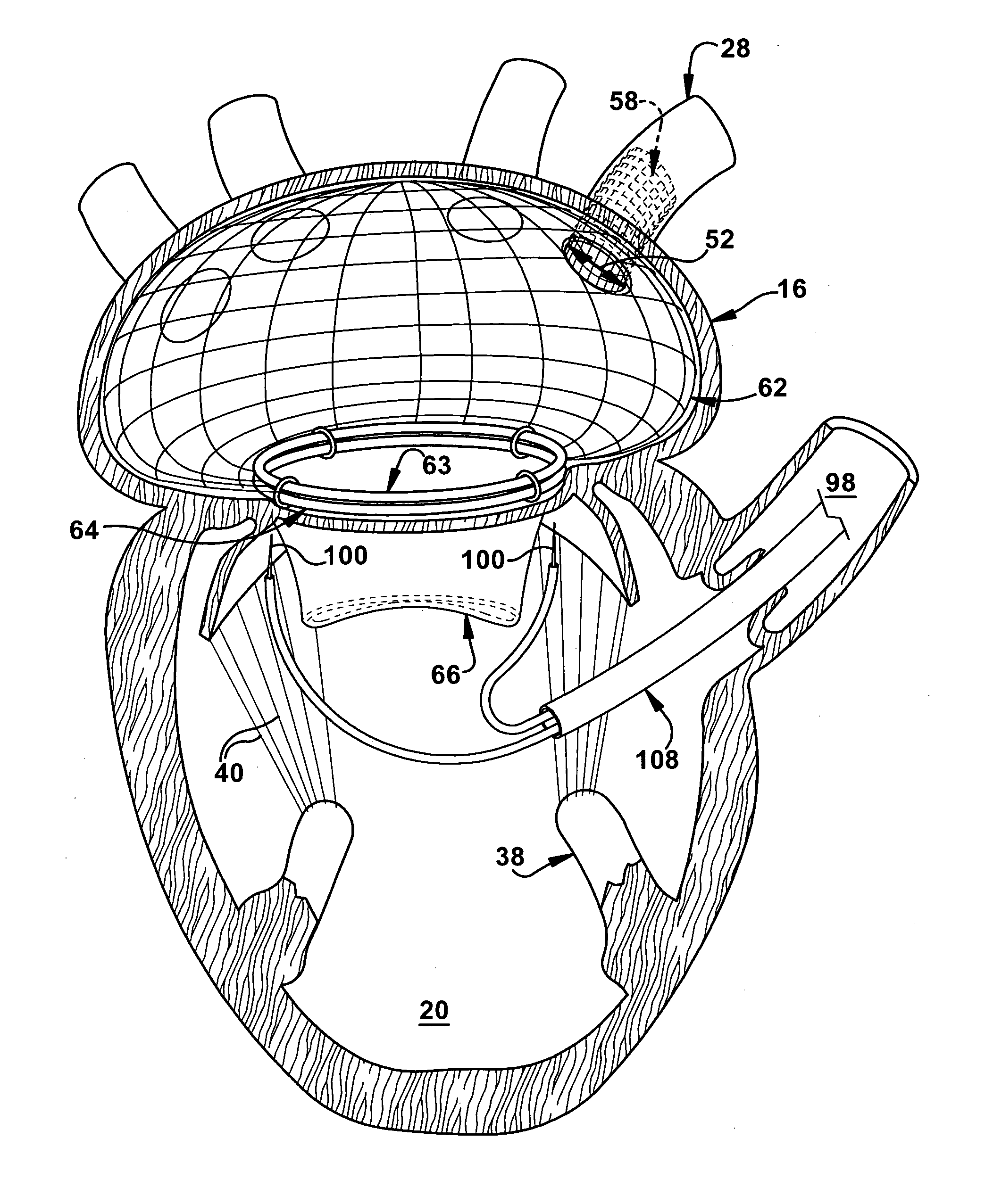
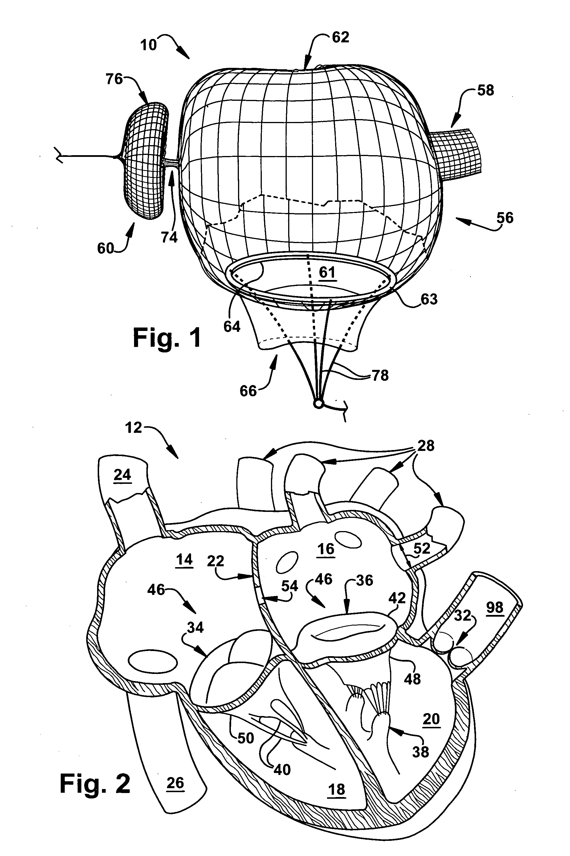
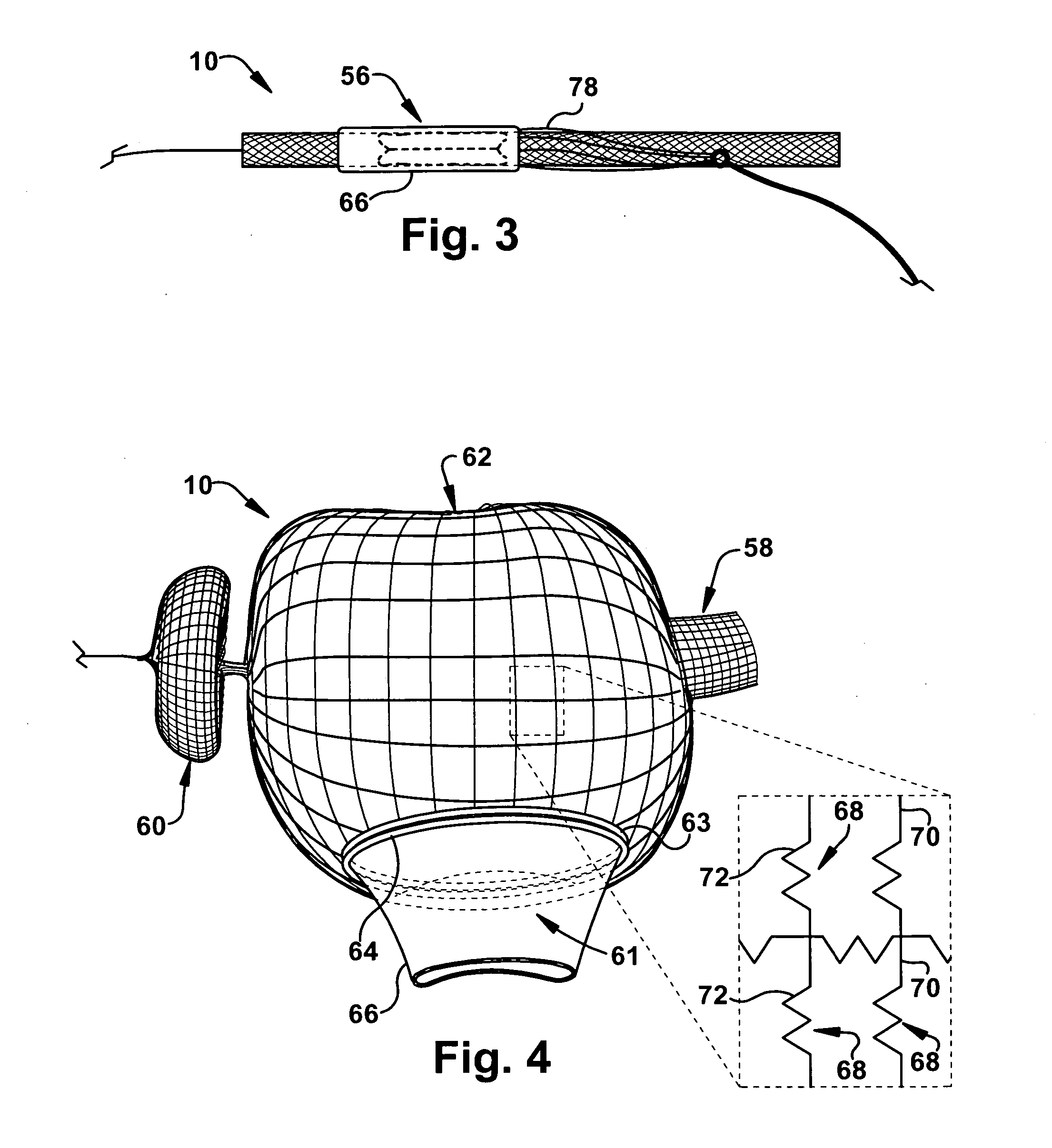
[0031] The present invention relates to an apparatus and method for replacing a cardiac valve, and is particularly directed to an apparatus and method for the correction of mitral and tricuspid valve disorders via a minimally invasive, percutaneous approach. As representative of the present invention, FIG. 1 illustrates an apparatus 10 for replacing a diseased cardiac valve 46 (FIG. 2), such as a mitral valve 36 or tricuspid valve 34.

[0032]FIG. 2 schematically illustrates a human heart 30 which includes four chambers: the right and left atria 14 and 16, respectively, and the right and left ventricles 18 and 20, respectively. The right and left atria 14 and 16 are divided by the interatrial septum 22. The thin-walled right atrium 14 receives deoxygenated blood from the superior vena cava 24, the inferior vena cava 26, and from the coronary sinus (not shown). The thin-walled left atrium 16 receives oxygenated blood from pulmonary veins 28. The right and left ventricles 18 and 20 pump...


PUM


Abstract

An apparatus for percutaneously replacing a diseased cardiac valve includes an expandable support member for positioning in an atrial chamber. The expandable support member includes at least one anchoring portion for anchoring in at least one opening that extends from the atrial chamber and a main body portion located adjacent the at least one anchoring portion. The main body portion has a cage-like structure and is adapted to conform to a size and shape of the atrial chamber. An expandable ring is selectively connected to the main body portion. The expandable ring is adapted to engage an annulus of the diseased cardiac valve. A prosthetic valve is attached to the expandable ring. The prosthetic valve is adapted to replace the diseased cardiac valve. A method for percutaneously replacing a diseased cardiac valve is also described.

Description

RELATED APPLICATION [0001] This application claims priority from U.S. Provisional Application No. 60 / 711,233, filed Aug. 25, 2005.TECHNICAL FIELD [0002] The present invention relates to an apparatus and method for replacing a cardiac valve, and is particularly directed to an apparatus and method for the correction of mitral and tricuspid valve disorders via a minimally invasive, percutaneous approach. BACKGROUND OF THE INVENTION [0003] There are two atrioventricular (AV) valves in the heart; one on the left side of the heart and one on the right side of the heart. The left side AV valve is the mitral valve and the right side AV valve is the tricuspid valve. Both of these valves are subject to damage and dysfunction requiring the valves to be repaired or replaced. [0004] The mitral and tricuspid valves differ significantly in anatomy. While the annulus of the mitral valve is generally D-shaped, the annulus of the tricuspid valve is more circular. The effects of valvular dysfunction v...

Claims


Application Information

Patent Timeline
IPC IPC(8): A61F2/24
CPCA61B2017/00243A61F2/2409A61F2/2418A61F2220/0016A61F2230/0076A61F2220/0066A61F2230/0065A61F2230/0071A61F2220/005
Inventor KAPADIA, SAMIRYADAV, JAYTUZCU, E. MURAT
Owner THE CLEVELAND CLINIC FOUND
Why Eureka
Try Eureka