Cleaner system

a cleaning system and cleaning technology, applied in the field of cleaning systems, can solve the problems of dust and debris discharged from the suction inlet, difficult to achieve effective utilization of the suction force generated by the suction station, and unclean floor of the room, so as to improve the dust removal performance of the docking station and improve the connection position and structur

Inactive Publication Date: 2007-07-12
SAMSUNG ELECTRONICS CO LTD
View PDF6 Cites 181 Cited by
  • Summary
  • Abstract
  • Description
  • Claims
  • Application Information

AI Technical Summary

Benefits of technology

[0011]Accordingly, an aspect of the present invention is to provide a cleaner system having an improved connecting position and structure between a robot cleaner and a docking station, thereby achieving an improvement in dust removal performance of the docking station.
[0012]It is another aspect of the present invention to provide a cleaner system which allows a user to perform manual cleaning by use of a docking station, which serves to remove dust and debris collected in a robot cleaner.

Problems solved by technology

However, the suction inlet, which is also used to suck dust and loose debris, has a broad width in order to efficiently suck the dust and loose debris, and therefore, is difficult to achieve an effective utilization of a suction force generated by the suction station.
Further, when the dust and loose debris are sucked from the robot cleaner into the suction station, the dust and debris, discharged from the suction inlet, tend to be caught by the brushes that are mounted in the proximity of the suction inlet of the robot cleaner.
The dust and debris, caught by the brushes, may make the floor of a room unclean when the robot cleaner again performs automatic cleaning.
Furthermore, the conventional cleaner system has a problem in that a suction channel for connecting the suction inlet of the robot cleaner to the suction unit of the suction station must be located below the robot cleaner when the robot cleaner docks with the suction station, and therefore, the oblique front surface of the suction station must have a high height.
This makes it difficult for the robot cleaner to dock with the suction station.

Method used


Image

  • Cleaner system
  • Cleaner system
  • Cleaner system

Examples


Embodiment Construction

[0032]Reference will now be made in detail to the embodiment of the present invention, examples of which are illustrated in the accompanying drawings, wherein like reference numerals refer to like elements throughout. The embodiments are described below to explain the present invention by referring to the figures.

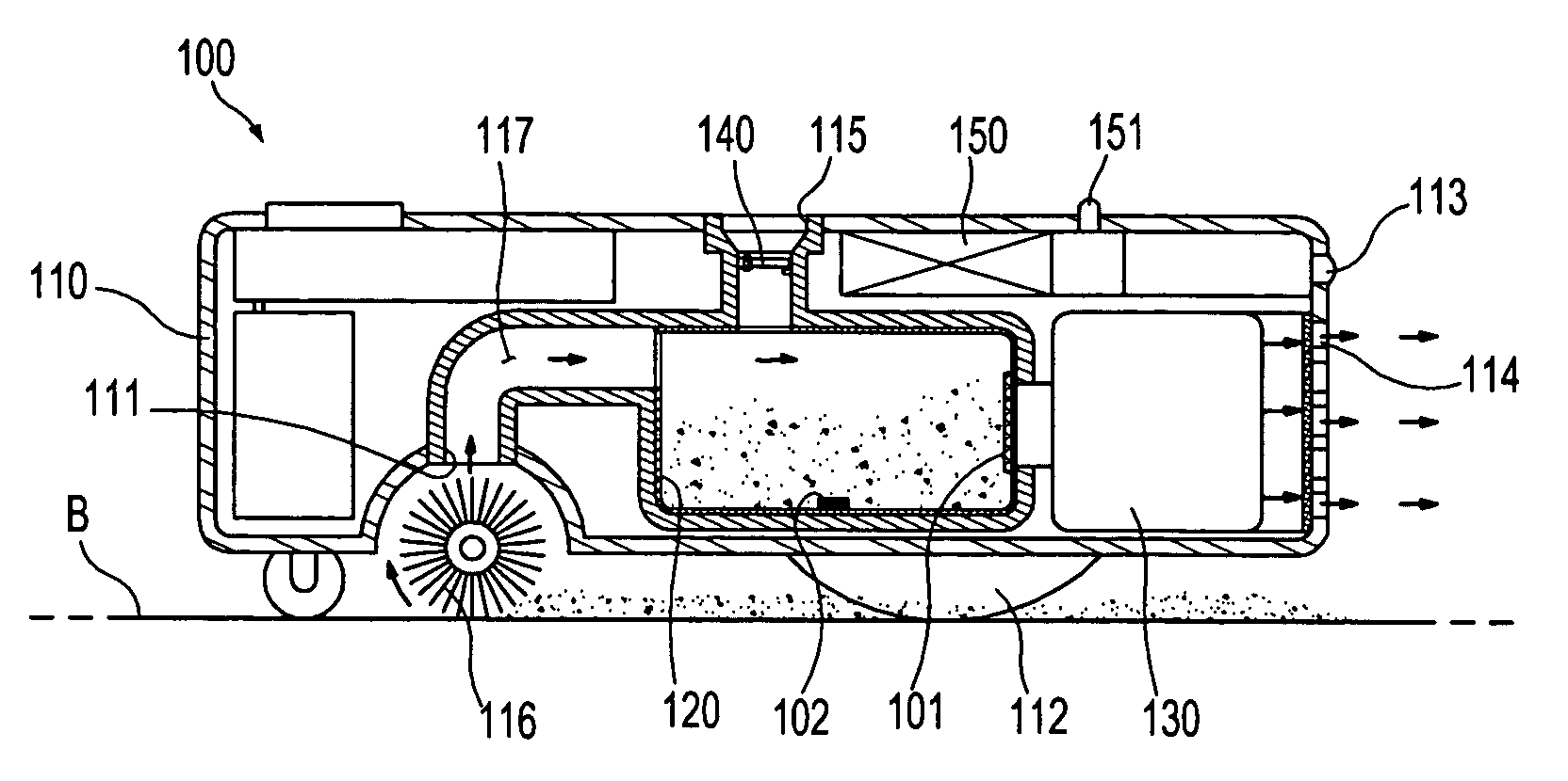
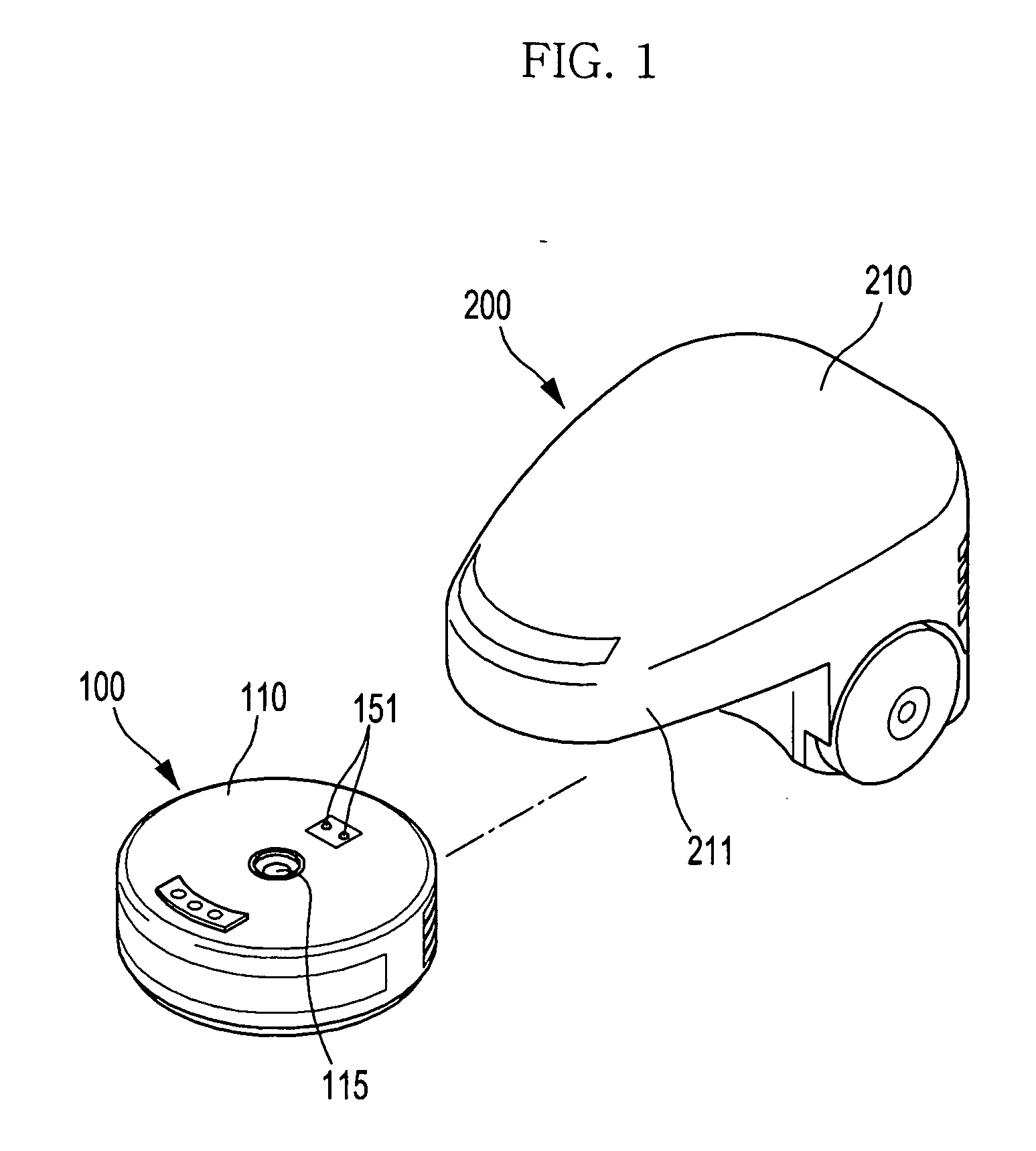
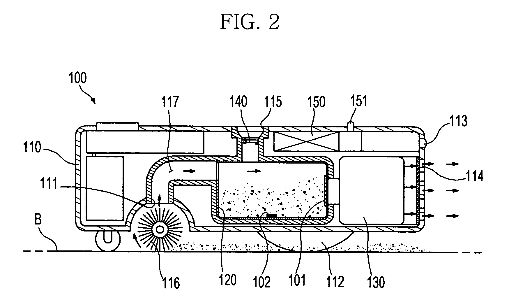
[0033]FIG. 1 is a perspective view illustrating an outer appearance of a cleaner system according to an embodiment of the present invention. FIGS. 2 and 3 are side sectional views illustrating a robot cleaner and docking station as shown in FIG. 1, respectively. FIG. 4 is a side sectional view of the cleaner system of FIG. 1, illustrating the robot cleaner and docking station coupled to each other.

[0034]As shown in FIGS. 1-4, the cleaner system according to an embodiment of the present invention, comprises a robot cleaner 100, and a docking station 200. The robot cleaner 100 includes a robot body 110 having an inlet 111 to receive dust and loose debris, and a first dust col...


PUM


Abstract

A cleaner system having an improved connecting position and structure between a robot cleaner and a docking station for achieving an improvement in dust removal performance of the docking station. The docking station performs manual cleaning. The robot cleaner has a dust outlet at a top wall of the robot body to discharge the dust collected in the first dust collector into the docking station, and the docking station has a connection port at a position thereof corresponding to the dust outlet to receive the dust discharged from the dust outlet. The robot cleaner or docking station includes a connector to connect the dust outlet to the connection port. The docking station includes a suction part, suction pipe, and suction hole for manual operation. A channel switching member is mounted in the docking station to selectively apply power required to suck dust to the connection port or suction hole.

Description

CROSS-REFERENCE TO RELATED APPLICATIONS[0001]This application claims the benefit of Korean Patent Application No. 10-2006-0001921, filed on Jan. 6, 2006 in the Korean Intellectual Property Office, the disclosure of which is incorporated herein by reference.BACKGROUND OF THE INVENTION[0002]1. Field of the Invention[0003]The present invention relates to a cleaner. More particularly, to a cleaner system having a docking station, which is provided to suck and remove dust and loose debris stored in a robot cleaner.[0004]2. Description of the Related Art[0005]A conventional cleaner is a device used to remove dust in a room for cleaning the room. A conventional vacuum cleaner collects dust and loose debris by a suction force generated from a low-pressure unit. Recently, a cleaning robot, which is designed to remove dust and loose debris from the floor while moving on the floor via without manual operation, has been developed. Hereinafter, a term “automatic cleaning” refers to a cleaning op...

Claims


Application Information

Patent Timeline
Patent Type & Authority Applications(United States)
IPC IPC(8): A47L5/00
CPCA47L5/225A47L9/106A47L9/2805A47L9/2873A47L2201/024A47L9/2889A47L2201/00A47L2201/022A47L9/2884B05B1/12B05B1/18B05B9/03B05B12/002B05B13/0278F16J15/32
Inventor LEE, JUN HWAJOO, JAE MAN
Owner SAMSUNG ELECTRONICS CO LTD
Why Eureka
Try Eureka