
Battery pack and electronic equipment

a battery pack and electronic equipment technology, applied in batteries data exchange, exchanging data chargers, transportation and packaging, etc., can solve the problem that electronic equipment will not determin

Inactive Publication Date: 2007-07-12
GK BRIDGE 1
View PDF2 Cites 17 Cited by
  • Summary
  • Abstract
  • Description
  • Claims
  • Application Information

AI Technical Summary

Benefits of technology

The present invention provides a battery pack that can be charged by electronic equipment that uses different methods to determine battery pack type. The battery pack includes a discrimination resistor and a controller with a discrimination section that allows the electronic equipment to determine the battery pack type. The battery pack also has a voltage source that can provide suitable charging voltage for each type of battery pack. This allows for constant voltage charging with the appropriate charging voltage based on the battery pack type. The technical effect of the invention is that it provides a more versatile and adaptable battery pack that can be used with different electronic equipment.

Problems solved by technology

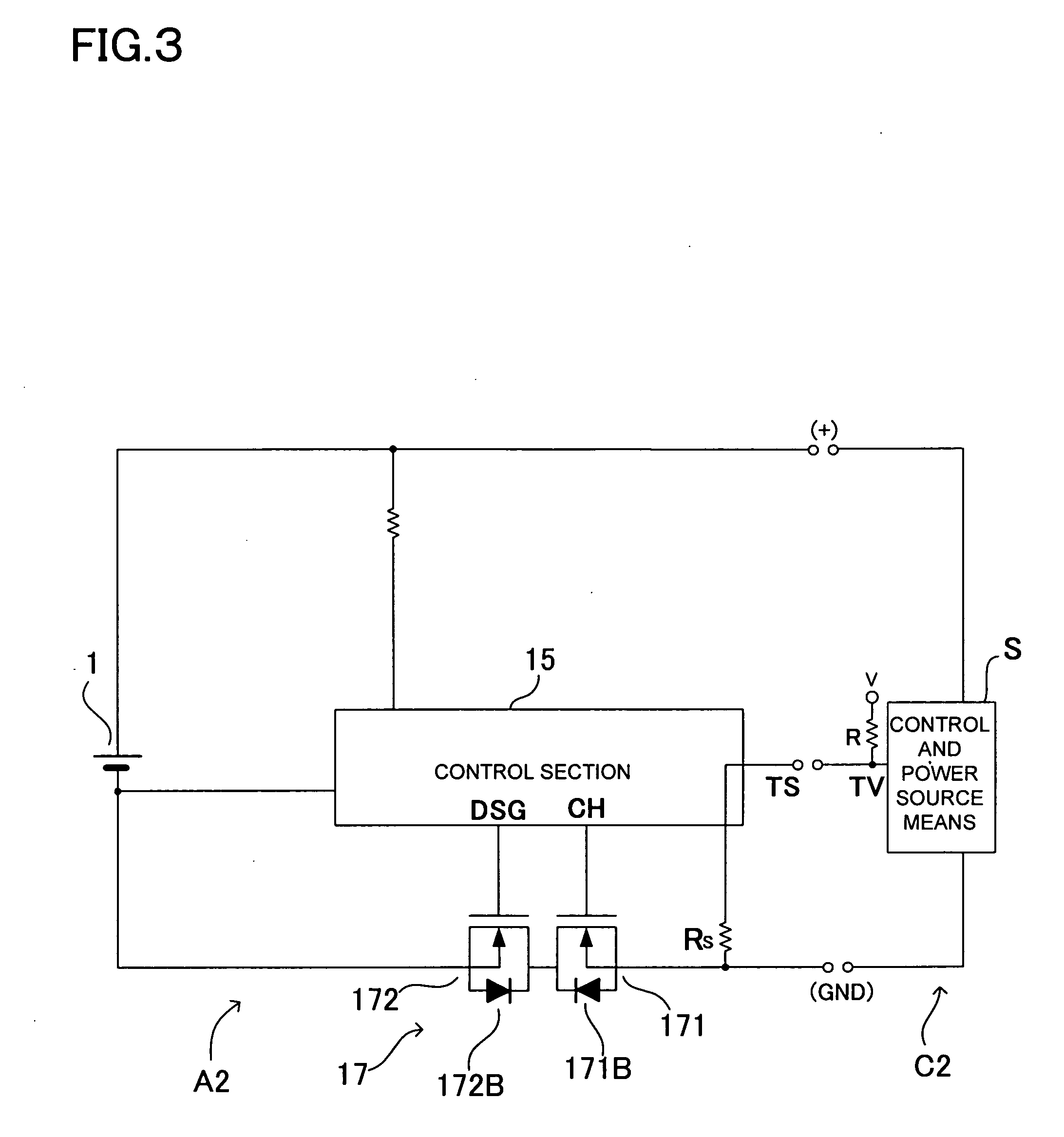
However, if electronic equipment provided with battery pack identification capability attempts to charge a battery pack that uses a discrimination resistor, the electronic equipment will not determine the battery pack is a preferred product because it cannot make battery pack identification via communication, and it will not perform charging.

Method used


Image

  • Battery pack and electronic equipment
  • Battery pack and electronic equipment
  • Battery pack and electronic equipment

Examples


Embodiment Construction

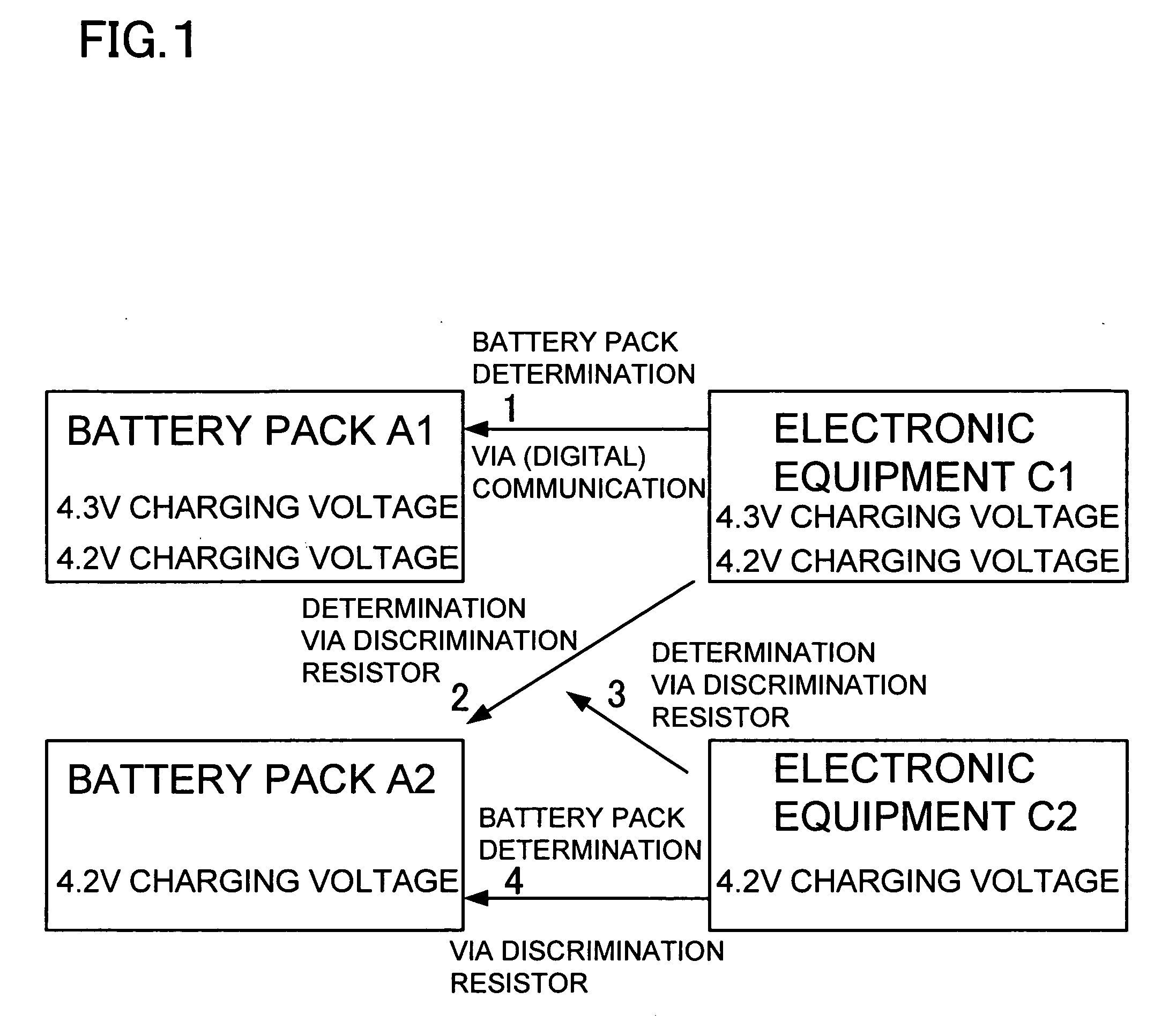
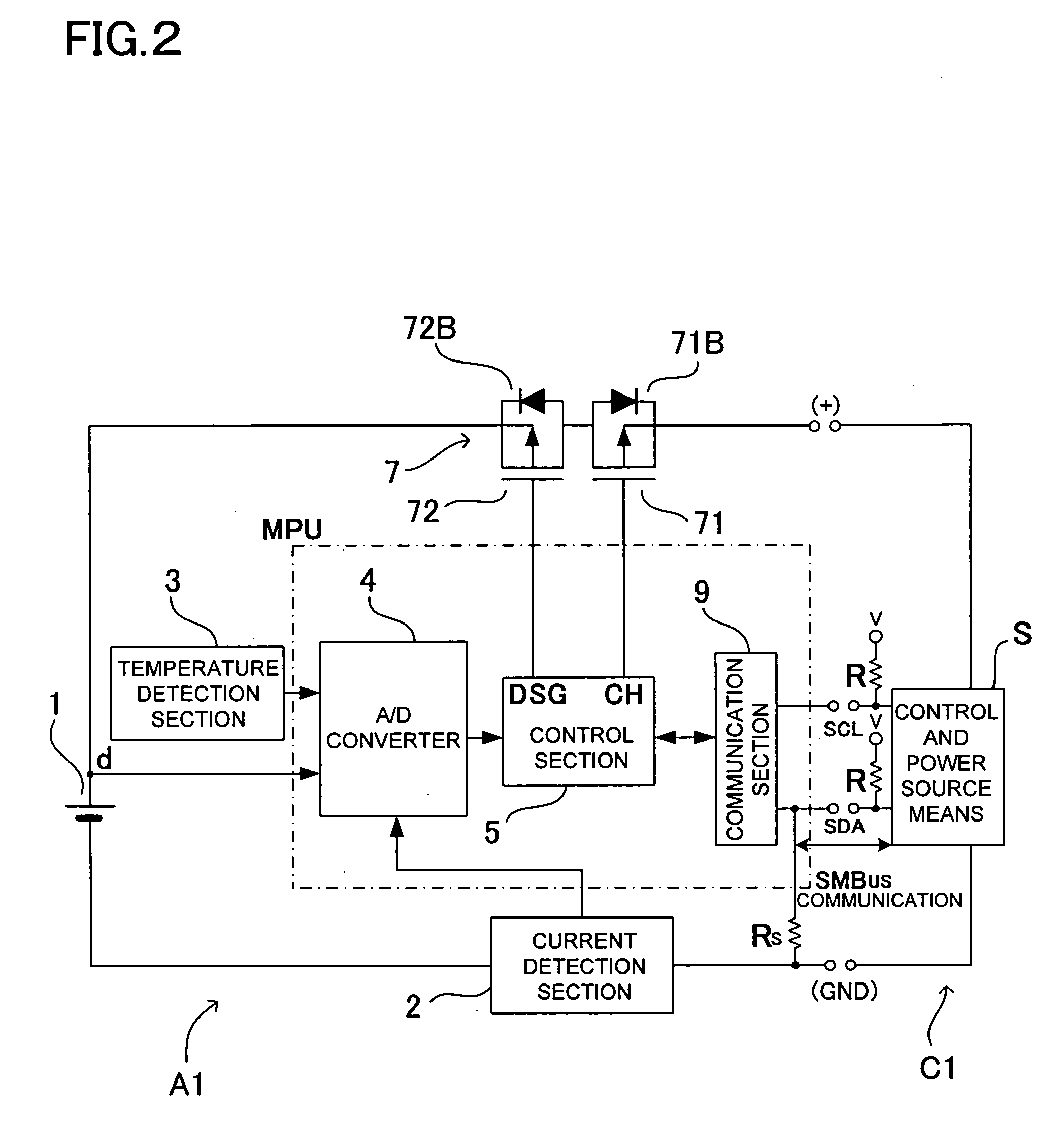
[0018] The following describes in detail embodiments of the present invention referring to the drawings. Summary of these embodiments is described referring to FIG. 1. A battery pack A1 of the present invention, which is provided with a discrimination resistor Rs and a controller having a (digital) discrimination function, and a battery pack A2 having a discrimination resistor Rs, which is used in prior art, can be used as the battery pack. The battery pack A1 houses lithium ion batteries 1 that can be charged at a high voltage (first charging voltage about 4.3V). The battery pack A2 houses lithium ion batteries 1 that can be charged at the prior art low voltage (second charging voltage about 4.2V).

[0019] The following electronic equipment contain a power source that charges lithium ion batteries 1 by well-known constant current, constant voltage charging, and can be used as electronic equipment with the capability to charge a battery pack. Electronic equipment C1 can be used, whic...


PUM


Abstract

The battery pack is charged by an electronic equipment and communicates with the electronic equipment. The battery pack is provided with a discrimination resistor electrically connected to communication lines, and a controller having a discrimination function for electronic equipment judgment of battery pack type from communication via the communication lines. The electronic equipment has a discrimination function that determines battery pack type utilizing the discrimination section of the battery pack controller. In addition, the electronic equipment has a discrimination function that applies voltage to the discrimination resistor to determine battery pack type.

Description

BACKGROUND OF THE INVENTION [0001] 1. Field of the Invention [0002] This invention relates to a battery pack and electronic equipment. [0003] 2. Description of the Related Art [0004] In prior art, a thermistor, which is a temperature-sensing element, is housed in the battery pack. Battery pack temperature is measured at the electronic equipment side (for example, at an electric tool, a battery charger, a notebook computer, etc.) via a temperature terminal, which is a battery pack connection terminal, and various types of control are performed. [0005] Meanwhile, battery packs with microprocessor units as controllers are provided with the ability to communicate with the electronic equipment side (refer to Japanese Patent Application Disclosure 2005-93109). This function allows capabilities such as computation and display of remaining capacity, and battery pack identification (ID), which confirms whether the battery pack is specified product (or preferred product, or authentic product)...

Claims


Application Information

Patent Timeline
Patent Type & Authority Applications(United States)
IPC IPC(8): H02J7/00H02J7/02
CPCH02J7/0006H02J7/0004H02J7/00038H02J7/00036H02J7/00047
Inventor TERAOKA, HIROKI
Owner GK BRIDGE 1
Learn More