Embedded inductor structure and manufacturing method thereof

a manufacturing method and inductor technology, applied in the direction of inductance/transformer/magnet manufacturing, inductance, inorganic material magnetism, etc., can solve the problems of limited number of turns of wound coils and inability to meet the requirements of element miniaturization, etc., to achieve higher current load, increase inductance, and increase the effect of turns

Inactive Publication Date: 2007-07-12
DELTA ELECTRONICS INC
View PDF2 Cites 29 Cited by
  • Summary
  • Abstract
  • Description
  • Claims
  • Application Information

AI Technical Summary

Benefits of technology

[0013] As mentioned above, according to the embedded inductor structure and the manufacturing method thereof according to the invention, a conductive wire is wound from the central portion to both ends in a helical manner to form a helically arranged coil. Compared with the prior art, the number of turns of the invention may be increased under the same dimensional constraints. Therefore, the structure has a higher inductance to handle a higher current load.

Problems solved by technology

So, the embedded inductor structure 1 is thicker and thus cannot meet the requirements of element miniaturization.
Furthermore, because the coil 11 cannot completely fill the space in which the coil 11 is wound, the number of turns of the wound coil is limited under the same specification.

Method used


Image

  • Embedded inductor structure and manufacturing method thereof
  • Embedded inductor structure and manufacturing method thereof
  • Embedded inductor structure and manufacturing method thereof

Examples


Embodiment Construction

[0023] The present invention will be apparent from the following detailed description, which proceeds with reference to the accompanying drawings, wherein the same references relate to the same elements.

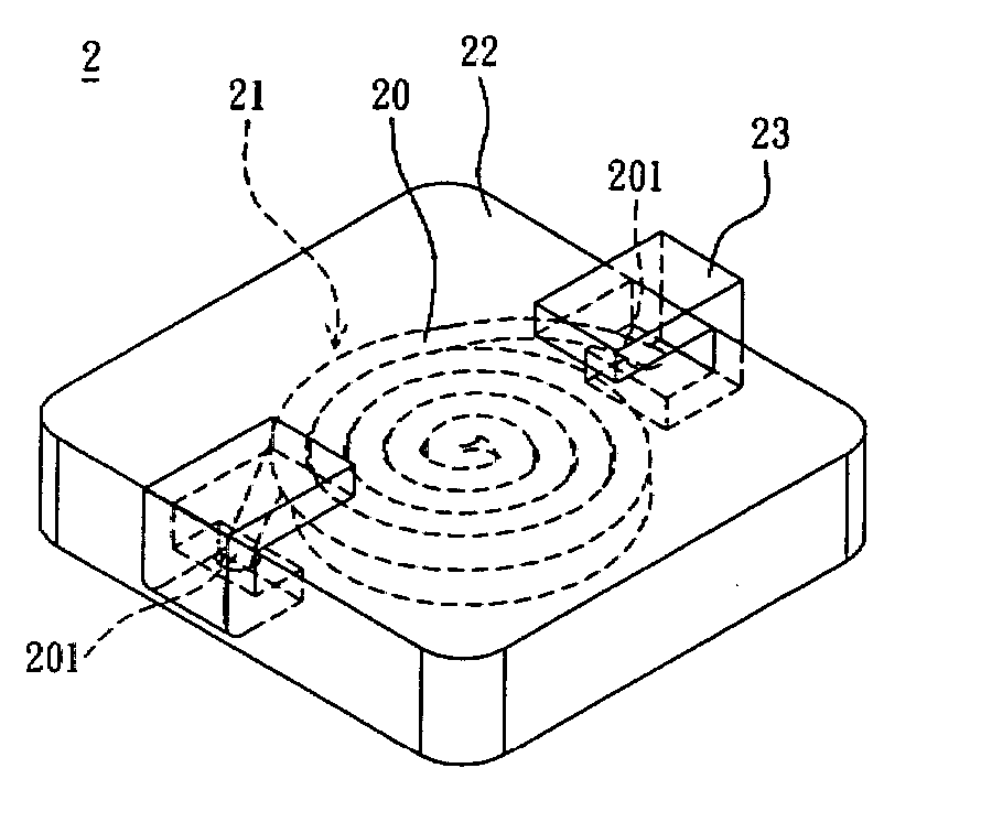
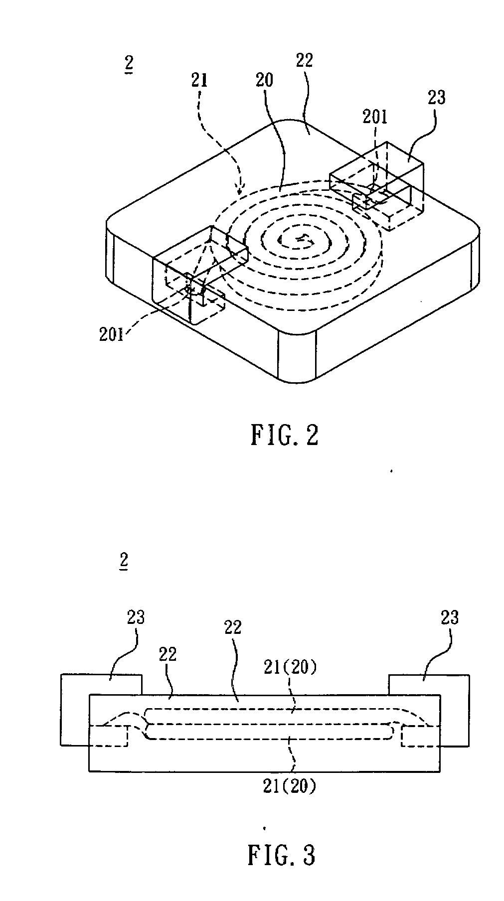
[0024]FIGS. 2 and 3 are a pictorial view and a side view showing an embedded inductor structure 2 according to a preferred embodiment of the invention. The embedded inductor structure 2 includes at least one coil 21, a magnetic body 22 and two terminals 23.

[0025] The coil 21 is formed by helically winding a conductive wire 20 from a central position to both ends 201 such that the coil 21 is tightly and helically coiled. Thus, the number of turns of the wound coil is increased to increase the inductance without increasing the bulk of the coil 21. Then, the ends 201 are respectively connected to the terminals 23 to serve as the structures to be electrically connected to an external circuit. The cross-sectional shape of the conductive wire 20 or each of the terminals 23 may be circula...


PUM

PropertyMeasurementUnit
angleaaaaaaaaaa
angleaaaaaaaaaa
angleaaaaaaaaaa

Abstract

An embedded inductor structure includes at least one coil and a magnetic body. The coil is formed by winding a conductive wire from a central portion to both ends. The coil is embedded in the magnetic body.

Description

CROSS REFERENCE TO RELATED APPLICATIONS [0001] This Non-provisional application claims priority under 35 U.S.C. § 119(a) on Patent Application No(s). 095101003 filed in Taiwan, Republic of China on Jan. 11, 2006, the entire contents of which are hereby incorporated by reference. BACKGROUND OF THE INVENTION [0002] 1. Field of Invention [0003] The invention relates to an embedded inductor structure and a manufacturing method thereof, and, in particular, to an embedded inductor structure formed by helically winding a coil from the central portion to both ends, and a manufacturing method thereof. [0004] 2. Related Art [0005] With the miniaturization of electronic products, the fundamental components, such as inductor structures, also have to be miniaturized to meet the trend of element miniaturization. [0006] Referring to FIG. 1, a conventional embedded inductor structure 1 has a coil 11, a magnetic body 12 and two terminals 13. Two ends of the coil 11 are respectively connected to the ...

Claims


Application Information

Patent Timeline
Patent Type & Authority Applications(United States)
IPC IPC(8): H01F27/02
CPCH01F1/26H01F27/255H01F2017/048H01F27/327H01F41/127H01F27/292
Inventor HUANG, NENG-KUEIKAO, CHING-MANHSU, HAN-CHENG
Owner DELTA ELECTRONICS INC
Why Eureka
Try Eureka