Display apparatus adapted for a display wall, image adjustment method therefor and display wall therewith

Inactive Publication Date: 2007-07-12
DELTA ELECTRONICS INC
View PDF14 Cites 10 Cited by
  • Summary
  • Abstract
  • Description
  • Claims
  • Application Information

AI Technical Summary

Benefits of technology

[0013] An object of this invention is to provide an image adjustment method adapted for a display wall comprising a plurality of display apparatuses. A video signal is received by each display apparatus of the display wall separately. Based on an arranged position in the display wall, each display apparatus captures a part of the image frame of the video signal according to an initial setting and then scales it to be displayed on a digital display element of the display apparatus, wherein the display apparatuses set a horizontal display length and a vertical display length according to the resolution of adopted digital display elements. In one embodiment for a horizontal tuning process, either a right side or a left side of the image of the display apparatus of the display wall is fixed and a horizontal capture image length is then adjusted. In another selected embodiment for a vertical tuning process, either a top side or a bottom side of the image of the display apparatus of the display wall is fixed and a vertical capture image length is then adjusted. The displayed image of each display apparatus is adjusted sequentially to keep a whole image consistency of the neighbored images displayed by the display wall. By using the image adjustment method of this invention, the displayed image can achieve a very high precision degree. For example, while adjusting the horizontal capture image length of the displayed image of the display apparatus, the adjustment is in a unit of an increment or a decrement of a pixel. While adjusting the vertical capture image length of the displayed image of the display apparatus, the adjustment is in a unit of an increment or a decrement of a line. Consequently, a quite well quality is achieved for the whole neighbored images displayed by the display wall by using this invention.

Problems solved by technology

The preset scaling modes are not suitable for adjusting image for individual display apparatus used in the display wall.
A drawback in such way is that a precision degree to adjust the output image relates to the current scaling factor of the image.
Consequently, the adjustment method cannot keep continuity of the displayed image between neighbored display apparatuses.
The major image discontinuity is due to the image scaling problem in multiplication of fraction numbers.
Consequently, choosing 341 pixels for scaling results in a shortage of some part of the displayed image; choosing 342 pixels for scaling results in a replication of some part of the displayed image.
These lead to the image discontinuity between neighbored display apparatuses among the display wall.
However, the difference between horizontal and vertical scaling aspect ratios of the image will cause the loss in maintaining horizontal and vertical aspect ratio of the image to be displayed.
However, an empty area is left in the surrounding area of the display screen.
However, the preset scaling modes cannot be applied for the display wall applications.

Method used


Image

  • Display apparatus adapted for a display wall, image adjustment method therefor and display wall therewith
  • Display apparatus adapted for a display wall, image adjustment method therefor and display wall therewith
  • Display apparatus adapted for a display wall, image adjustment method therefor and display wall therewith

Examples


Embodiment Construction

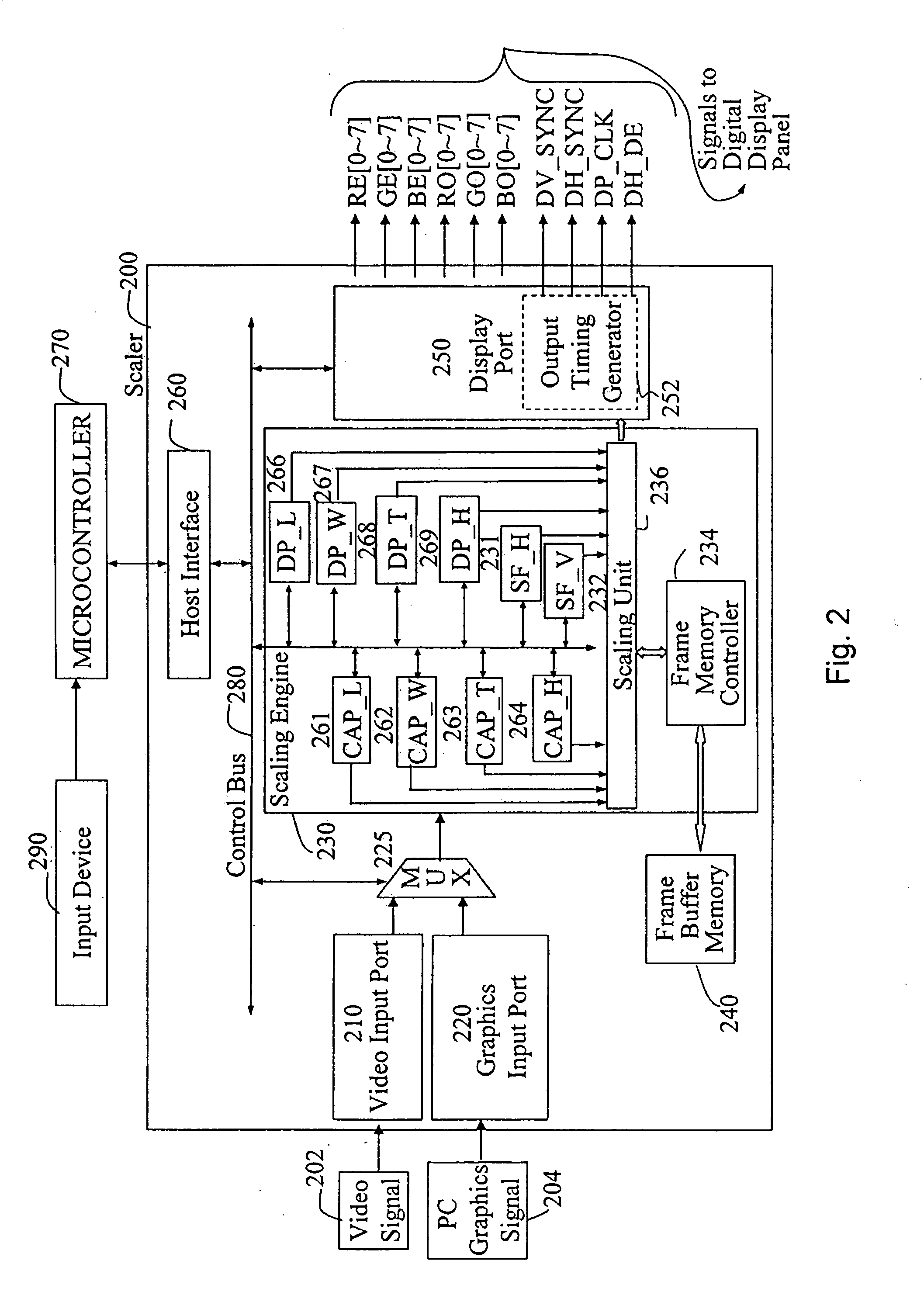
[0027] Please refer to FIG. 2 which is an internal circuitry block diagram of a scaler disclosed in this invention. In this circuitry, a video input port 210 receives a video signal 202 input externally and a graphics input port 220 receives a computer video signal 204 input externally. A selection switch 225 selects one of the inputs between the video input port 210 and the graphics input port 220 and transmits the selected input signal to a scaling engine 230 after video decoding and / or analog-to-digital (A / D) converting of the selected input signal. Wherein, video input port 210 performs the video decoding and A / D converting functions for the video signal 202 and the graphics input port 220 performs the A / D converting function for the computer video signal 204. The term “video” is used, hereafter, to refer to a video including a computer video in a broad sense in the following specification.

[0028] The scaling engine 230 is coupled to a frame buffer memory 240 which serves the sc...


PUM


Abstract

A display apparatus adapted for a display wall, an image adjustment method therefor and a display wall therewith are provided. The image between display apparatuses of the display wall is not exactly displayed, especially for adjacent areas between every two neighbored display apparatuses, and the displayed image is required to be adjusted for the defects. The image adjustment method includes receiving a video signal and then setting an initial image capture area in a scaler of each of display apparatuses in the display wall for selecting and scaling a part of the video image and transmitting the part to a digital display element of the display apparatus for display. Then based on the whole image displayed on the display wall by combining the image displayed on each of the display apparatuses, sequentially adjusts the image displayed by each of the display apparatuses. While adjusting the size of the image, one side of an image capture area is fixed and the length of the image capture area is adjusted. A scaling factor is simultaneously updated according to the adjusted length of the image capture area. The precision degree for the adjusted images can be a pixel in a horizontal direction and a line in a vertical direction for the displayed images and a complete and more perfect image can be obtained by the adjustment method.

Description

BACKGROUND OF THE INVENTION [0001] 1. Field the Invention [0002] The present invention relates to a display apparatus adapted for a display wall, an image adjustment method therefor and a display wall therewith, specifically to a digital display apparatus adapted for a display wail, an image adjustment method and a display wall therewith. [0003] 2. DESCRIPTIONS OF THE RELATED ART [0004] In recent years, display walls were popularly used in occasions with large-scale displays. The display wall is arranged by combining several display apparatuses together. Each display apparatus selects a part of image according to the corresponding arranged position and scales to a full-screen size of the display apparatus. All the combined display apparatuses therefore jointly display a whole image of the input signal. [0005]FIG. 1 is a diagram of a display wall consisting of 3×3 display apparatuses. In FIG. 1, 100 is a video source and 111, 112, 113, 121, 122, 123, 131, 132 and 133 are nine display...

Claims


Application Information

Patent Timeline
IPC IPC(8): G09G5/00
CPCG06F3/1446G09G5/005G09G5/006G09G2340/0478G09G2340/0414G09G2340/0421G09G2340/0471G09G2320/08G09F9/35
Inventor YANG, JUNG-YICHEN, FANG-TIENFAN, CHANG-HSIEN
Owner DELTA ELECTRONICS INC
Why Eureka
Try Eureka